Analysis of a Hybrid Structural System: Reinforced Concrete Columns and Steel Roof Trusses
In many wide-span structures, reinforced concrete columns and steel roof trusses are commonly used together due to economic reasons. However, the different characteristics of these two materials can lead to unusual behaviors at their connection points and in the overall system.
In this article, we will analyze the seismic behavior of an example system:
1. System Description
- Roof Truss:
- Span: 30 meters,
- Material: Steel.
- Columns:
- Height: 8 meters,
- Material: Reinforced concrete.
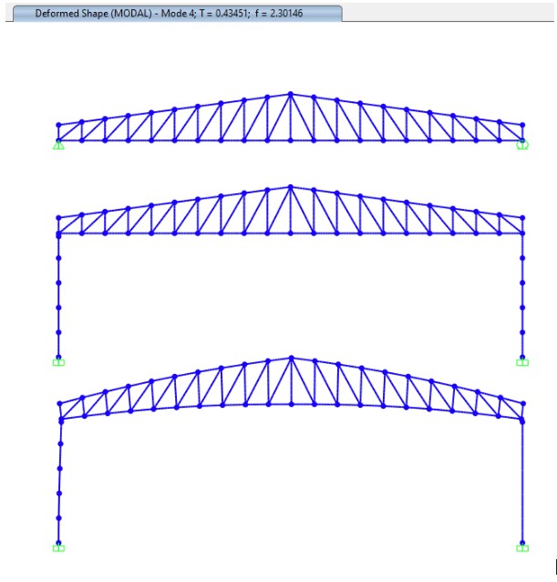
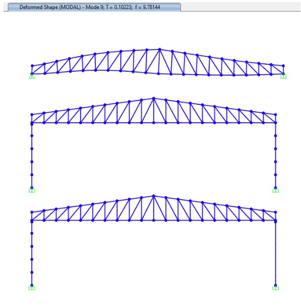
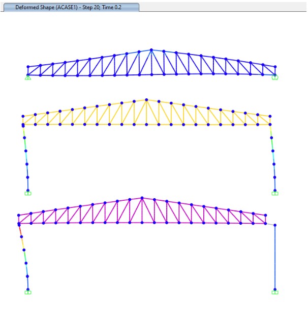
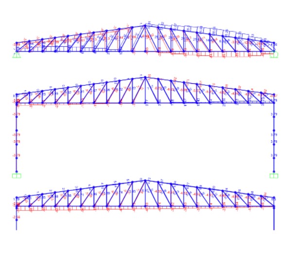
Case 1 Roof System Separate Solution: One of the supports is fixed and the other is movable: 1. Mode T=0.44 sec. Vertical
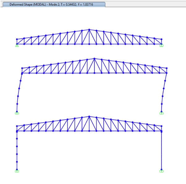
Case 2 Solution with Roof System: Both supports are fixed. Moment free at the upper ends of the column: 1. Mode T=0.54 sec. Horizontal
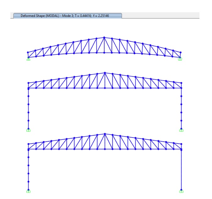
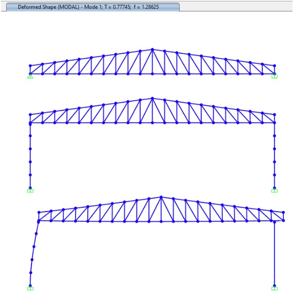
Case 3 Roof System Solution Together: One of the supports is fixed and the other is movable. Moment is free at the upper ends of the column. With the LINK element on the right column, the horizontal movement of the steel roof is provided independently of the column.: 1. Mode T=0.77 sec. Horizontal
Vertical earthquake movement in wide-span roofs should be taken into account at least with the mode combination method, as emphasized in the earthquake regulations. Since the vertical period of the roof truss in the 2nd and 3rd cases does not change compared to the 1st case, we can say that all 3 systems will behave similarly in the vertical earthquake.
In the column and roof truss interface, the periods will increase when using materials with relatively lower vertical rigidity such as elastomer.
In the first case, where the reinforced concrete and roof system are solved separately and then combined within the scope of general practice in the sector, since the first horizontal vibration period is T = 0.1 sec, it will be necessary to work with the maximum values in the horizontal elastic design spectrum in the equivalent earthquake load and mode combination method.
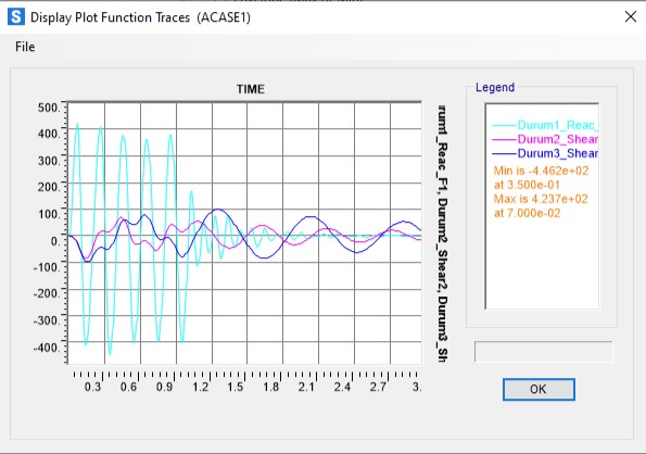
When a horizontal dynamic loading with a period of 1 second is applied to see the dynamic response of the structures, the following situations are observed.
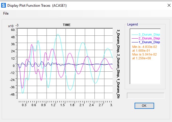
Horizontal Displacement at Moving Support Point
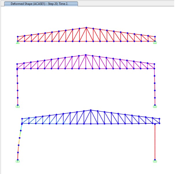
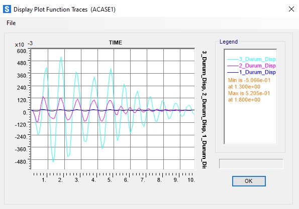
While the 3rd Case, whose natural vibration period is closest to the period of the applied force, makes a lot of displacement compared to the other cases, the 1st Case, whose horizontal natural vibration period is the farthest with 0.1 sec, makes the least displacement.
Therefore, it is understood that if the system is separated into parts and solved as in Case 1 and one of the supports is designed as sliding, the displacements will be on the unsafe side according to Case 3. The left column, which has to support all the horizontal force alone, has already entered the nonlinear region with a displacement of approximately 6%. Case 2, where both supports are designed as fixed, gives a result closer to Case 1.
Horizontal Reaction on Fixed Support, Left Columns Upper End Shear Force
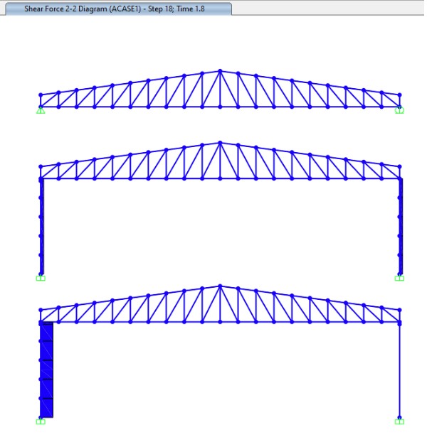
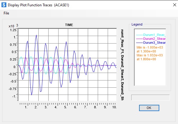
In Case 3, all the shear force in addition to the period effect comes to a single column. In Cases 1 and 2, the values appear very close to each other.
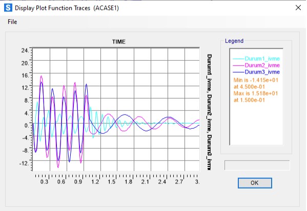
Roof Ridge Point Acceleration
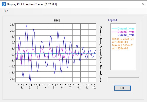
When looking at the accelerations, it is understood that the roof is almost motionless in Case 1. The acceleration value in Case 3 is twice that in Case 2, although there is no big difference in the natural vibration periods. In Case 3, the acceleration is approximately 2.5 g.
Alternatively, in case of dynamic horizontal loading in a period of 0.2 seconds, closer to the period of Case 1:
The displacement in Case 1 is the least, while Cases 2 and 3 appear to be closer to each other. The displacement of 480 mm in Case 3, which was loaded for a period of 1 second, has decreased by approximately 1 in 10.
While the horizontal reaction force in Case 1 has almost doubled, the shear force in Case 2 has halved and Case 3 has decreased to about one-tenth.
According to these values, when a structure with a real case of 3 is solved separately for the roof and columns, the shear forces in the 0.2-second period loading are calculated 4 times more, while the displacements are calculated 4 times less.
When the acceleration values are examined, it is seen that the values increase in Case 1 according to the 1-sec period loading, and the values in Cases 2 and 3 decrease.
Modal Combination
The following situations are observed with the response spectrum method, with the Sds value being approximately 1g.
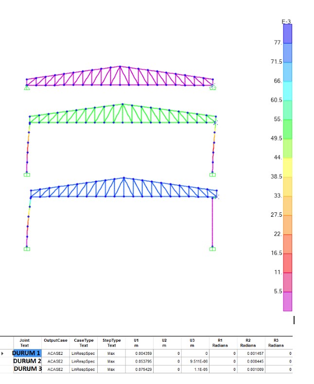
The displacement in Case 3 is about 19 times that in Case 1, and the displacement in Case 2 is about 14 times that in Case 1.
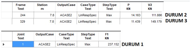
The shear force of Case 1 is twice as much as that of Case 2, and the shear force values of Cases 2 and 3 are close to each other.
When looking at the axial forces of the steel roof truss, the internal force in Case 1 is 4 times that of Case 2. Although the maximum pressure forces in Case 3 and Case 1 are at the same level, the shape of the internal force diagram is quite different.
When the results are examined, it is seen that the inclusion of columns in the system and the support conditions change all calculation values, and it is seen that it would be best to model the system as a whole as close as possible to the real situation, as required by the Earthquake Code. The column and the steel roof must be in harmony not only in terms of loads but also in terms of displacements.
According to ASCE, although the forces coming to the roof floors independent of the structural system are around 0.85 SDSW, these forces can reach up to 2.40 SDSW when multiplied by the excess strength coefficient of 2 for reinforced concrete connections and if the structure importance coefficient is 1.5.
Therefore, the forces coming to the roof should not be reduced by R and should be increased for connections to reinforced concrete.