The suspension bridge is one of the oldest and most widely used technologies, because it comes from a very simple idea: when you meet an obstacle, hang a rope strong enough between its two sides and cross. Materials and forms change, but the idea stays the same.
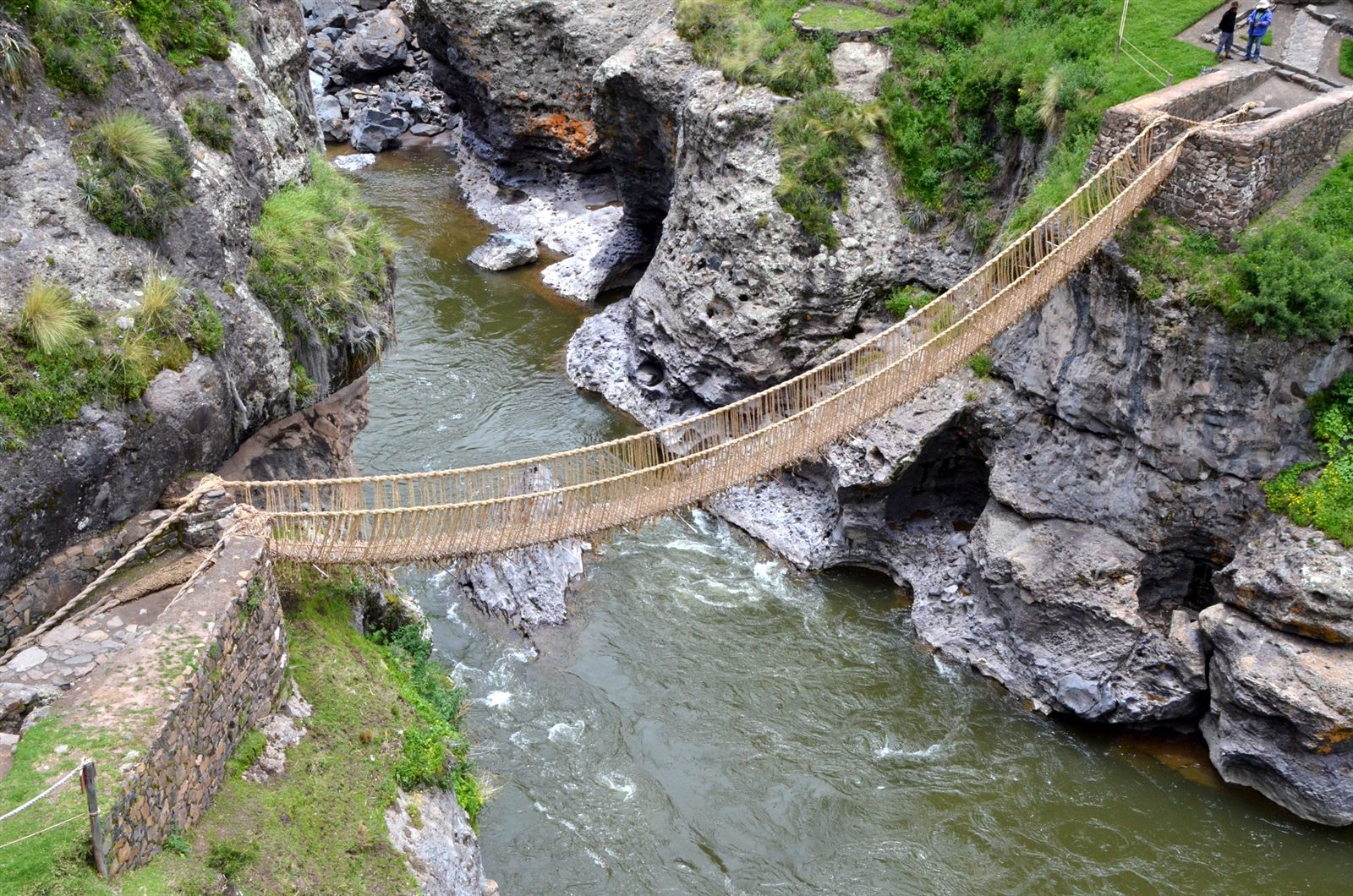
The Incas, for example, build suspension bridges from ropes made of grass gathered next to the bridge site and twisted into fibres. The material lasts a year at most, so the work has to be repeated every year. People gather on a day declared a bridge-building festival and make fibre and rope together. They weave from both sides of the bridge, and when the two halves meet in the middle there is great celebration. The old bridge, with a last moment of respect, is released into the river. The Incas also did arithmetic and stored numbers with knots tied in these fibres, so the bridge they build is a kind of abacus you can walk on.
With physics reaching down to the quantum level, bridges could hardly stand still. Stress ribbon bridges rest on the same simple idea as other suspension bridges, but they are far more complex and advanced than the bridges of the Incas. Despite their simple, plain appearance, they need much more careful and detailed analysis and design than many other bridges.
The system was devised by the German structural engineer Ulrich Finsterwalder and first proposed for a bridge across the Bosphorus.
Cable instead of girder
In a stress ribbon bridge, the main load-bearing members are high-strength cables. Over a 30 m span, a uniform load of 3 tonnes per metre can be carried by a steel girder only if it is 1 m deep; that girder weighs about 8 tonnes. The same load can be carried by a steel cable just 50 mm in diameter weighing half a tonne. The cables used in today’s bridges can take stresses 6–8 times higher than structural steel sections. To carry the load, however, the cable sags, and in doing so it applies very large horizontal forces to its end anchorages. This is why stress ribbon bridges today are generally built for pedestrians.
The deck is usually made of precast concrete elements, no more than 500 mm thick at their thickest point. The precast elements are first left to stand for a while to reduce shrinkage effects, then hung on the main cables and pulled along them into position.
Concrete is then cast in place to protect the main cables and the post-tensioning tendons inside the deck, to close the joints between deck elements and to give a smooth deck surface.
Finally, the precast elements are compressed with the post-tensioning tendons so that no tensile stress develops in the concrete under any load case.
With the extra mass of the concrete deck, the bridge is much less affected by dynamic actions such as pedestrian and wind loads.
Wide spans can be crossed quickly and with a minimum of material, without intermediate piers and without scaffolding for erection.
Analysis
Stress ribbon bridges are analysed with staged construction analysis. Including the time-dependent behaviour of the concrete is essential.
The stiffness of the steel cables changes at every stage with the load they carry; their behaviour is nonlinear. Ambient temperature also has a strong effect on the cable stresses.
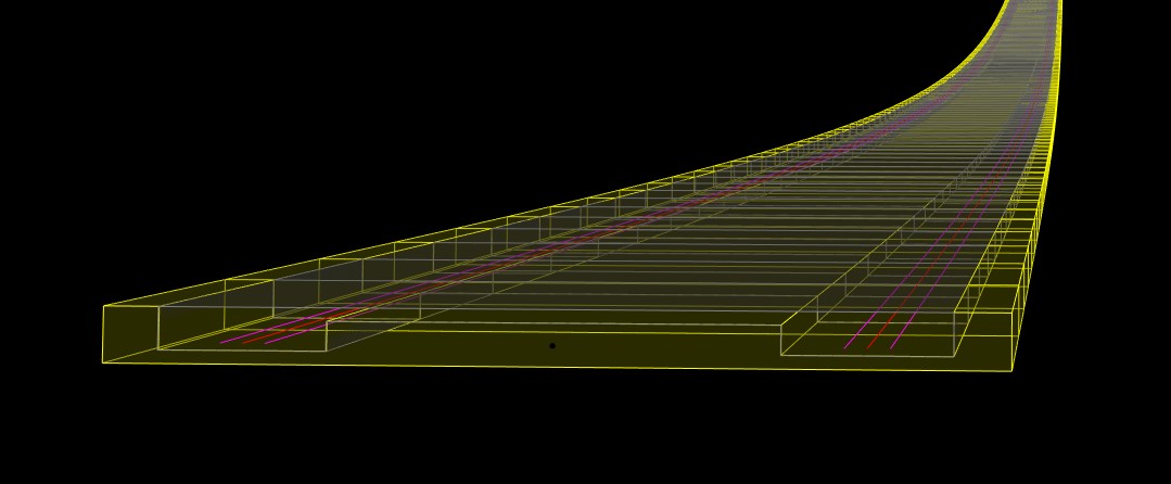
The model below is a stress ribbon footbridge with a 128 m span and a width of 4 m. Its steel cables weigh 35 tonnes and it uses 80 m³ of concrete. The maximum slope along the deck is 8%. The video shows its construction stages.

More from real projects: Case studies — steel projects told in the order they happened: where the input came from, what broke, what the engineer decided, with the numbers.
Related notes: Analysis and Design of Orthotropic Deck Steel Pedestrian Bridge · Design of Steel Network Arch Bridge · Cable-Stayed Steel Pedestrian Bridge Analysis and Design
Originally published in 2021; revised in 2026.