Bridges designed for pedestrians can be far more slender, lighter and more varied in form than road bridges designed for heavy vehicles. Because of this, they need many additional calculations and checks that other structures do not need at the design stage.
Construction stages
As with any structure, a bridge must first be able to carry its own weight. Once it is complete, the piers, deck, cables and so on all work together, so carrying the load is relatively easy. While the bridge is being built, however, its members are loaded differently from the final state, usually without help from other members, and temporary supports may be needed.
A main girder, for example, acts as a simple beam when it is first placed, as a continuous beam once it is joined to the others, and as a composite beam once a concrete slab is cast on top. In each state it sees different stresses and deformations, and these can stress the member far more than the final state does. Temporary construction loads add to this.
Cable-stayed steel bridges are statically indeterminate, so the force in one cable affects all the others. The stress–strain behaviour of cables is nonlinear, so their stiffness changes with their stress level. Tensioning a cable changes the geometry of the structure, and the geometry of the structure changes the tension in the cable. It is therefore essential to decide in which order, at which stage and by how much each cable is tensioned, to control the geometry of the bridge throughout construction, and to keep the computer model in step with the work on site, stepping in when needed. The final strength and geometry of the bridge depend on the construction stages being designed and carried out correctly, which means on the bridge first being built correctly in the computer model.
Pedestrians and vibration
After construction, the bridge opens to pedestrians. For landmark bridges the opening day matters a great deal: it may bring the largest live load of the bridge’s whole life.
When the Millennium Bridge in London opened in 2000, 90,000 people crossed it on the first day. Once the crowd reached a critical size, the horizontal component of the crowd’s movement synchronised with the bridge’s lateral vibration mode, causing large lateral sway. People could barely stay on their feet by holding on to the handrails. The bridge was closed two days later and reopened only after about two years of testing, research and added dampers. Since then, these effects have been taken into account in the design of footbridges.
Vertical vibration has been a design check for much longer. On long-span, narrow, lightweight footbridges, the natural frequency of the bridge can be close to the walking frequency of pedestrians, and unless the resulting vibrations are kept below certain comfort limits they can disturb people. Like many human actions, pedestrian load is both very simple and very complex. Its static part is similar to other live loads, but in its dynamic part many factors change its frequency and amplitude: walking speed, how many people walk in a group, their weight, their shoes, their stride length and more.
This has produced many dynamic pedestrian load models, defined differently in different codes. Comfort limits also vary from person to person, so the codes set different limits.
Wind
Mention wind and bridges, and most engineers think of the Tacoma Narrows Bridge. Its engineer, Leon Moisseiff, was innovative and bold. He designed the longest and most flexible bridge of his time: a main span of 853 m carried by main girders only 2.4 m deep. Opened in 1940, the bridge collapsed a few months later after excessive oscillation in a relatively low wind of 68 km/h. No error was found when its static calculations were checked, but Moisseiff never got over the loss of his bridge; he died of a heart attack in 1943. When the bridge was rebuilt, the girder deck was replaced by a truss about 10 m deep.
The disaster was a turning point for bridge–wind interaction, and research into the dynamic effects of wind began. Together with the growth of aeronautics and space science, it gave rise to aeroelasticity, the theory of how wind and flexible structures interact.
As the butterfly-effect metaphor has it, a butterfly flaps its wings and a few weeks later a storm breaks somewhere else. How air will move, at what speed, in which direction, at what frequency and at what height, can only be described with probability and statistics. Many researchers have therefore proposed quite different dynamic wind load models.
Eurocode EN 1991-1-4 does not fully cover cable-supported bridges, but it gives guidance on some checks for preliminary design.
For example, the structural factor cscd may be taken as 1 only if the frequency of the structure is above 5 Hz, which long-span cable-supported footbridges generally do not satisfy. The structural factor must then be determined using Annex B or Annex C.
Annex E gives formulas for aeroelastic instability checks. They give the critical wind speeds at which stability problems begin, based on the relevant frequency of the structure, its damping ratio and its section properties. Comparing these with the design wind speeds at the site checks the stability of the structure. Some instabilities, such as the one at Tacoma Narrows, must be avoided entirely; for others the code recommends more detailed calculations that include their effects, and wind tunnel tests.
Annex F gives formulas for the dynamic characteristics of the structure.
The example model
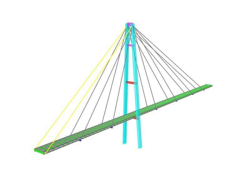
The model below is a cable-stayed steel footbridge, 108 m long in total, with a 71 m main span and a 42 m pylon. The video shows a nonlinear time-history earthquake analysis.
Related notes: Analysis and Design of Orthotropic Deck Steel Pedestrian Bridge · Stress Ribbon Bridge · Design of Steel Network Arch Bridge
Originally published in 2021; revised in 2026.