As bridge spans grow, the self-weight of the structure starts to dominate the design. Every millimetre of asphalt or deck concrete, even the weight of the safety barriers and the lighting, can change the bridge sections. That is why concrete, whose weight-to-performance ratio is far higher than that of steel, is avoided in the decks of long-span bridges. Concrete cracks, creeps and shrinks. Over the service life of a long-span bridge such concrete members may have to be replaced and renewed many times, which is very costly and time-consuming.
In 1948 Dr. Cornelius, a German engineer working at MAN, patented the orthotropic deck. In an orthotropic deck, vehicle or pedestrian loads are carried by a steel deck plate, stiffened by plates or sections welded to it along the length of the bridge, to cross beams placed at intervals across the bridge. The same plate can act together with the main girders and cross beams, or on its own.
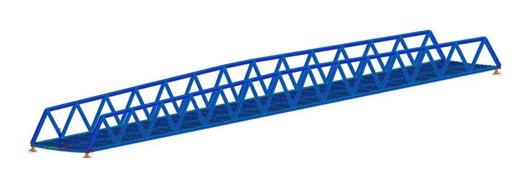
On footbridges the steel plate can be covered with a protective surfacing a few millimetres thick; heavy traffic needs an asphalt surfacing. With suitable paint and protection systems, the steel plates can reach a service life of up to 100 years.
Because the deck is lighter, the piers, the foundations and any supporting cables can be sized far more economically.
The example model
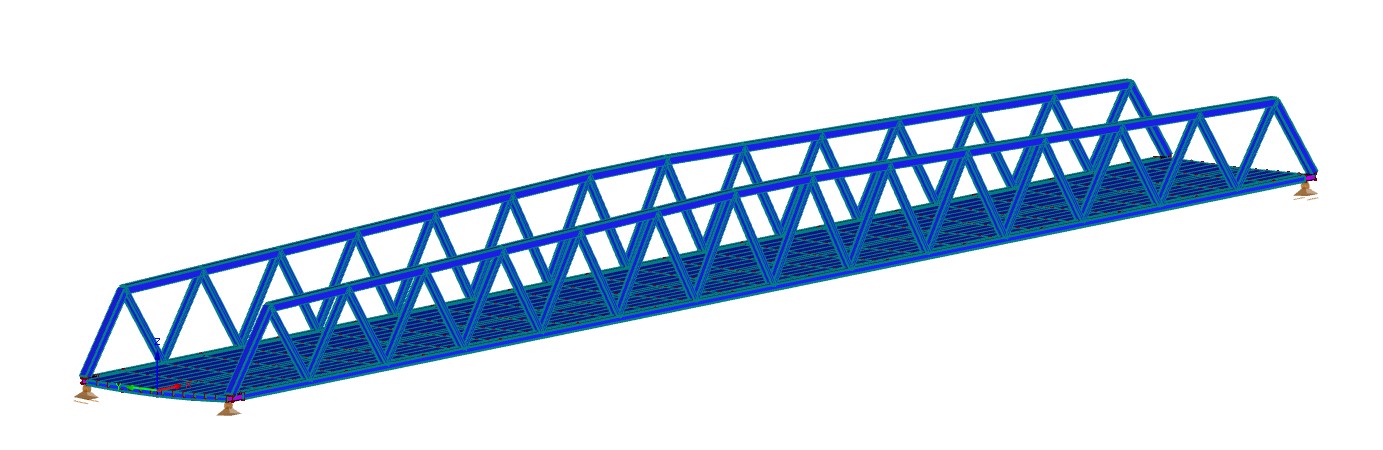
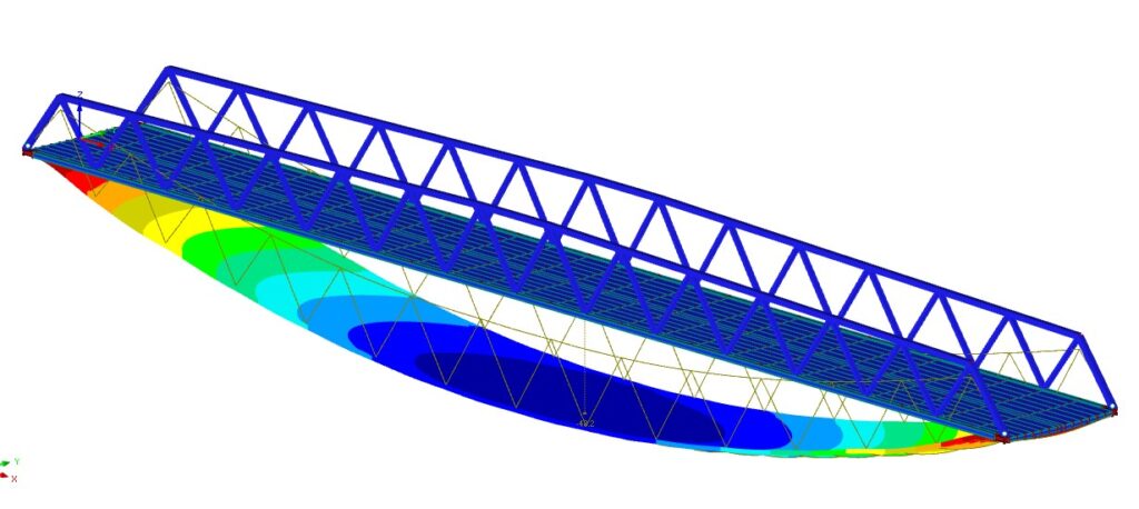
The model shown here is a 52 m steel footbridge with truss main girders and an orthotropic deck. Below: its deflection, and its vibration under pedestrian load.
Related notes: Stress Ribbon Bridge · Design of Steel Network Arch Bridge · Cable-Stayed Steel Pedestrian Bridge Analysis and Design
Originally published in 2021; revised in 2026.