

Calculation reports you can check, page by page
A calculation report is where an engineer decides whether to trust the numbers. I write mine to be checked: every result points to the section that derives it, every load is proven to have entered the model, and every assumption is stated where it is used. Below are pages from a real project’s report, anonymised: a steel entrance canopy and two guard booths. Further down: the same structure as a 3D model you can query member by member, and twelve connections from other delivered projects, coloured by stress.
Calculation reports
Inside the report
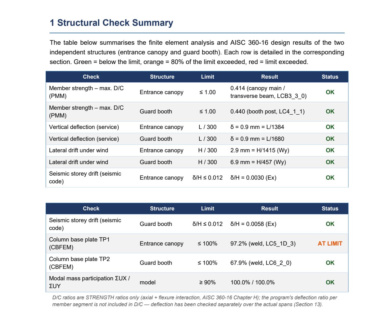
One table answers “does it pass?”
The report opens with every check, the structure it applies to, the limit, the governing result and the combination that produced it. Each row is worked out later in its own section, so the summary is an index, not a claim.
The note under the table says what the D/C ratio includes: strength only. Deflection is checked separately over the real spans. One base plate weld sits at 97% and is marked at limit, not rounded away.
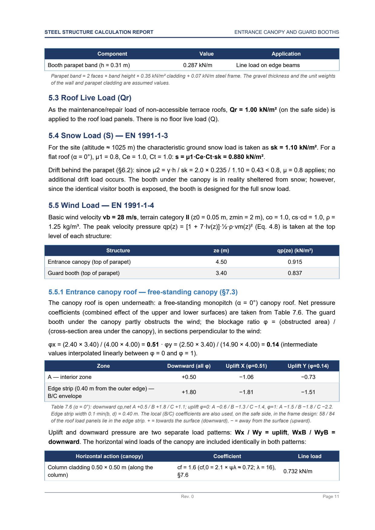
Loads derived, not just listed
Snow and wind are derived step by step, with the clause that governs each value. For the open canopy roof the net pressure coefficients depend on how much the booth underneath blocks the wind, so the blockage ratio φ is calculated in both directions and the coefficients are interpolated between the code’s limits.
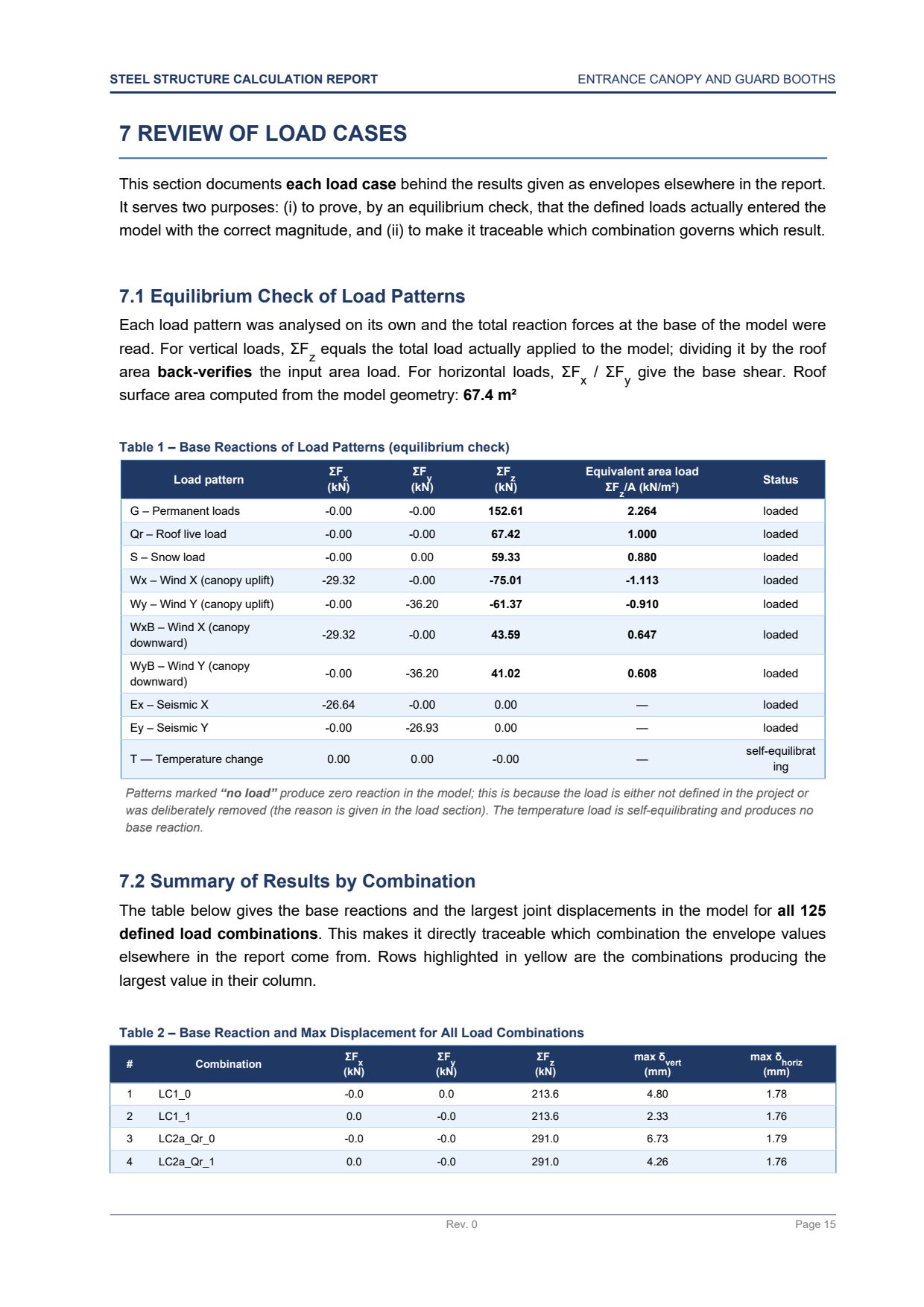
Proof that the loads entered the model
Every load pattern is solved on its own and its base reactions are summed. For vertical loads, the total reaction divided by the roof area has to give back the area load that went in: 1.000 kN/m² for roof live load, 0.880 kN/m² for snow. If a load were lost on its way into the model, this table would show it.
The next table lists all 125 combinations with their reactions and largest displacements, so every envelope value can be traced to the combination that produced it.
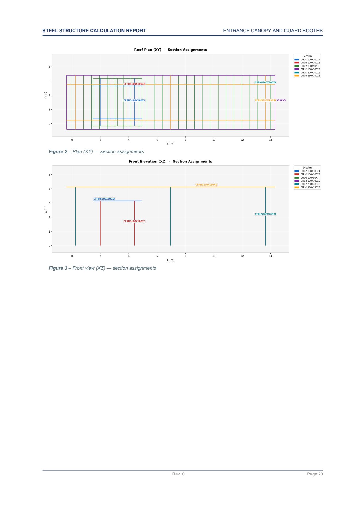
The model, drawn
Plan and elevations are coloured by section. The pages after them give joint and frame numbers, so any member named in a table can be found on a drawing.
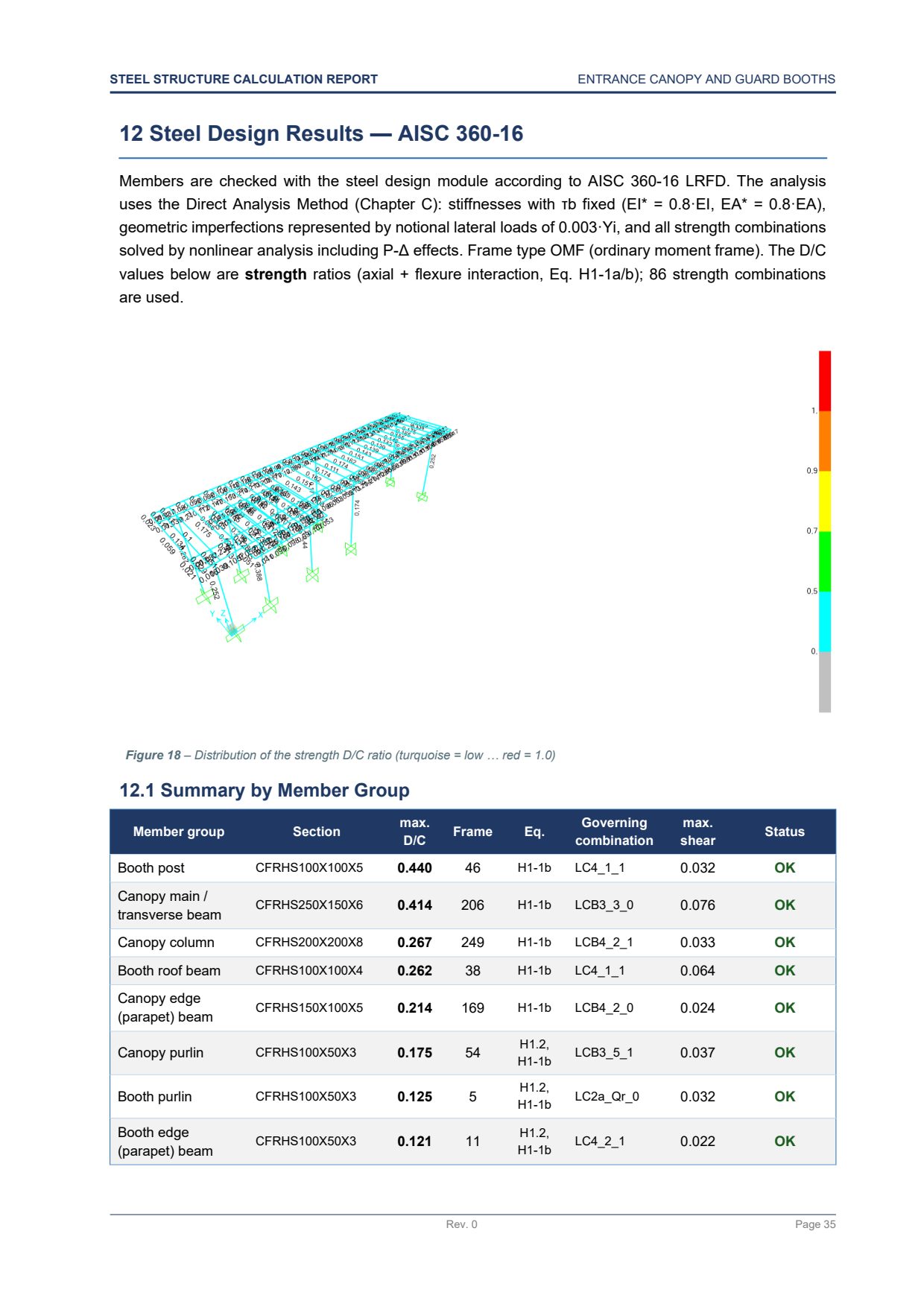
Design results, member by member
The D/C distribution over the whole model comes first, then a summary per member group: section, ratio, equation, governing combination and shear. The analysis follows the Direct Analysis Method with reduced stiffness and notional loads, and the text says so. A full table after this page lists every member, sorted by ratio.
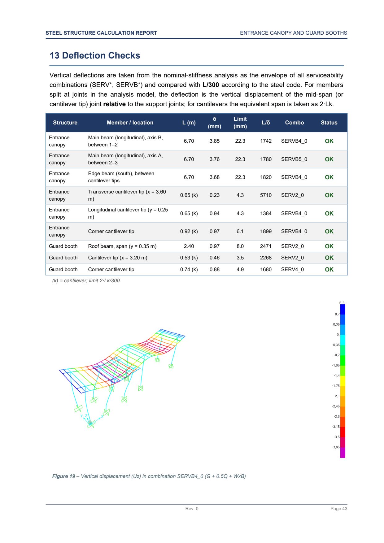
Deflection measured over the real span
An analysis model splits beams at every joint, so a deflection ratio per element says little. Here deflection is the displacement of the mid-span or cantilever-tip joint relative to its supports, over the real span, against L/300 — with the governing serviceability combination for each span.
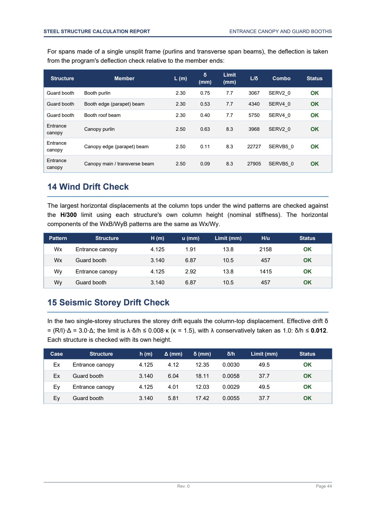
Drift under wind and earthquake
Column-top displacements under wind are checked against H/300, and seismic storey drift with the code’s amplification. Each structure is checked with its own height; the two are independent and the report keeps them apart.
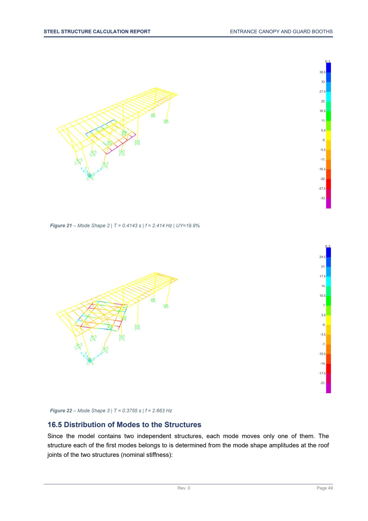
Modal behaviour
Mode shapes with period, frequency and mass participation. Because one model holds two independent structures, each mode is assigned to the structure that moves in it, so it is clear which period belongs to which building.
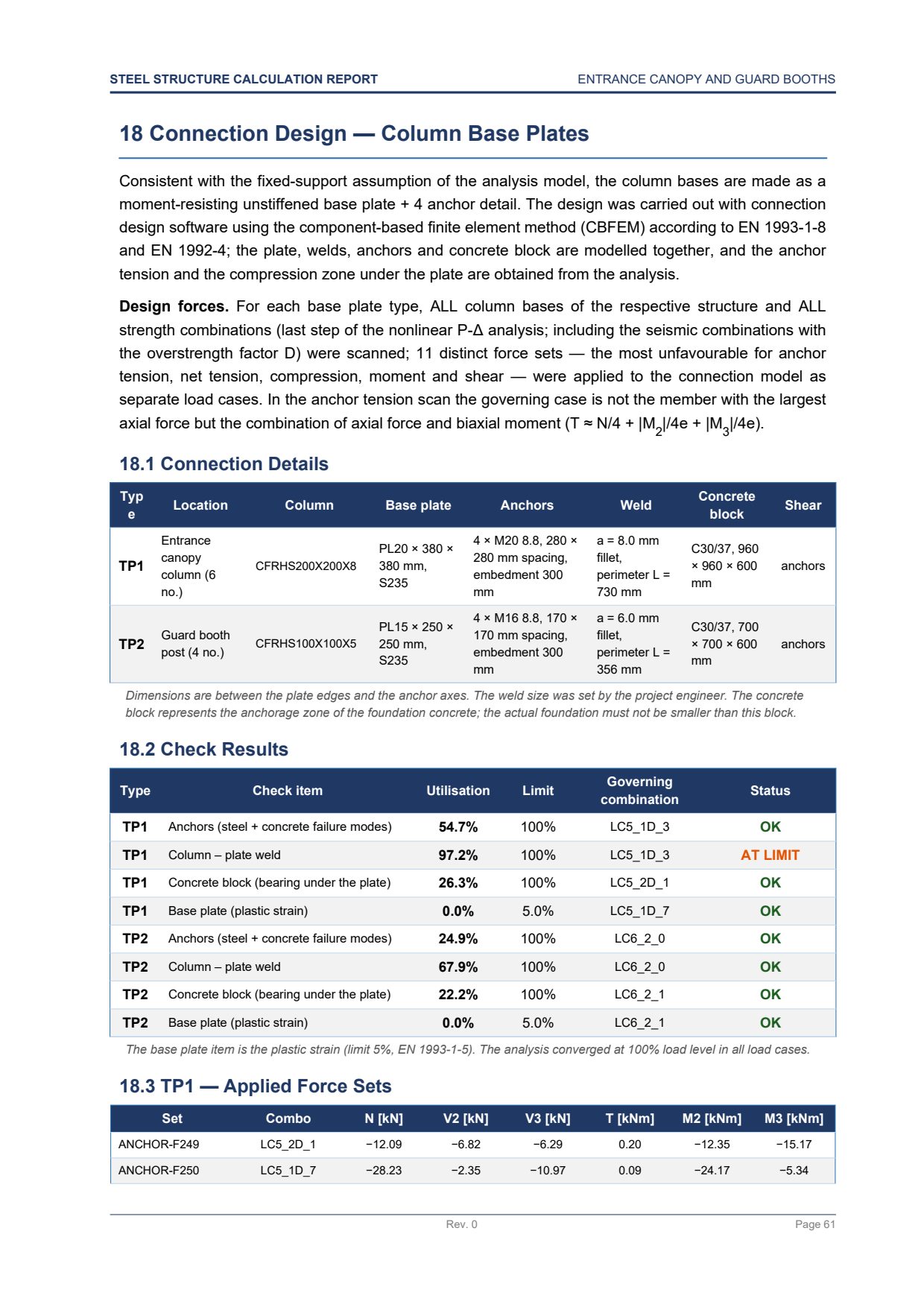
Connections checked with the forces that govern them
Base plates are designed with the component-based finite element method (CBFEM): plate, welds, anchors and concrete block in one model. All column bases and all strength combinations are scanned, and the force sets that govern anchor tension, compression, moment and shear go into the connection model as separate load cases.
In the full report the two connection calculations follow as appendices: 78 pages in total.
Explore the design, member by member
The structure from the report above, as a 3D model. Each of its 254 members carries its own design result. Tap or click a member to see its section, its strength ratio, the AISC equation and the load combination that govern it, and the report page where it is listed.
DESIGN EXPLORER
Pick a member
Drag to rotate, scroll or pinch to zoom. The list below starts with the members closest to their limit.
Highest ratios
Connections, coloured by stress
Each connection is modelled as what it is — plates, welds, bolts and anchors — and loaded with the governing forces from the analysis, then checked with the component-based finite element method. These twelve come from delivered projects. Under each: the utilisation of its components as the check reported it, and the plastic strain in the plates against a 5% limit.
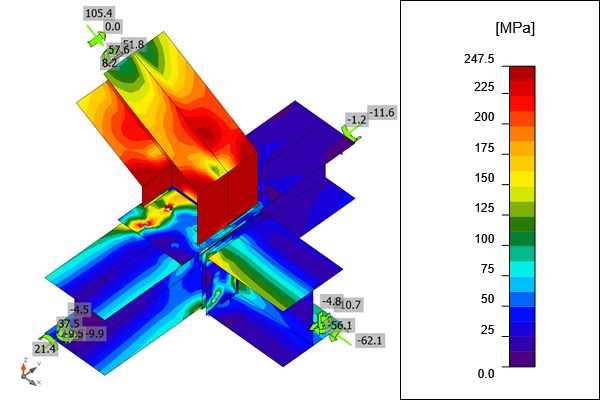
Haunched roof beam joint
HOTEL ROOF FRAME · AISC 360-16
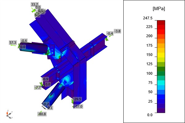
Brace node: tubes and beams at one column
HOTEL FRAME · AISC 360-16
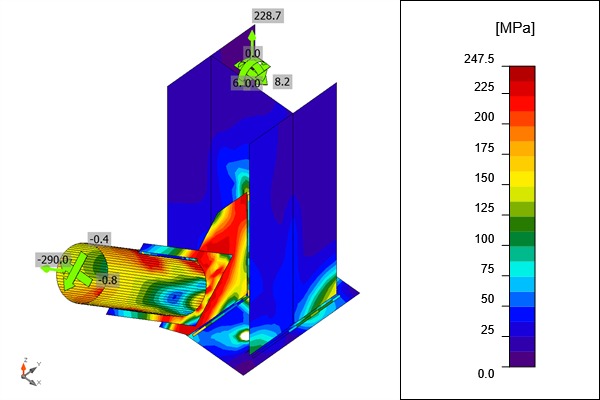
Tube brace on a column-base gusset
HOTEL FRAME · AISC 360-16
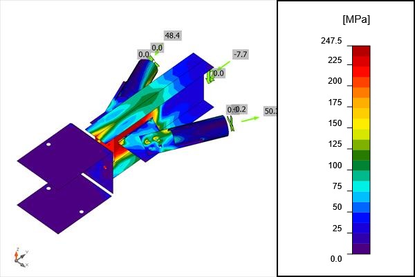
Twin tube braces on a base gusset
MEZZANINE FLOOR · AISC 360-16
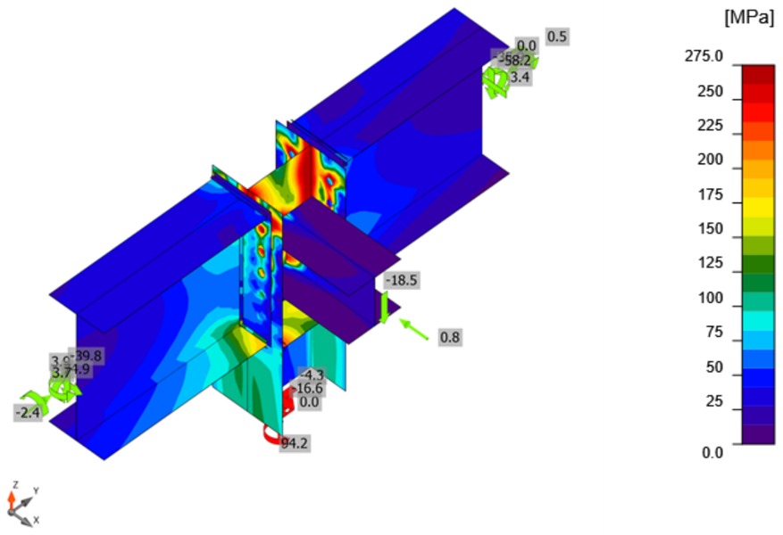
Bolted end-plate joint between two beams
MECHANICAL ROOM PLATFORM · EN 1993-1-8
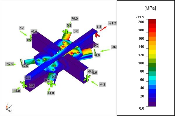
Cross joint with eleven bolts
ELEVATOR MACHINE ROOM FLOOR · AISC 360-16
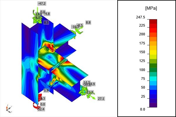
Multi-plate node
SHAFT WALL FRAME · AISC 360-16
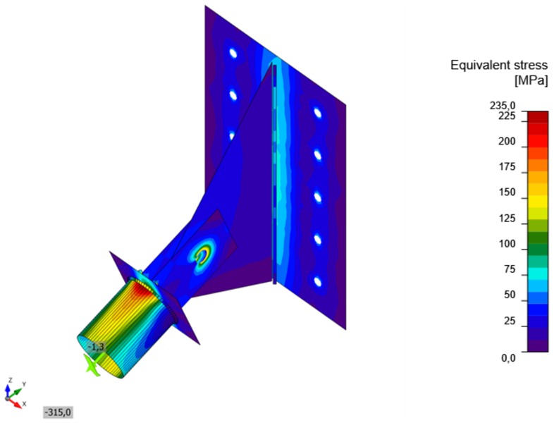
Inclined tube cantilever on an anchored wall plate
CANOPY · EN 1993-1-8
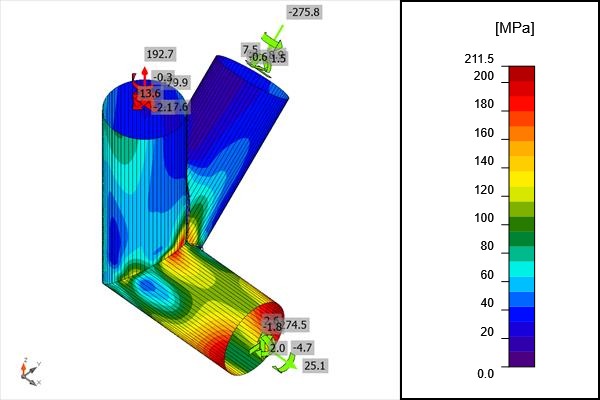
Mitred tube joint
BUSBAR PROTECTION FRAME · AISC 360-16
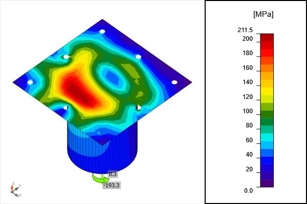
Circular column hung from a slab
BUSBAR PROTECTION FRAME · AISC 360-16
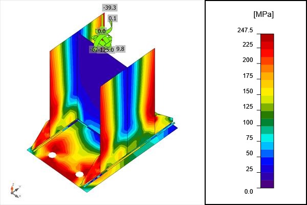
Stiffened base plate
ESCALATOR SUPPORT · AISC 360-16
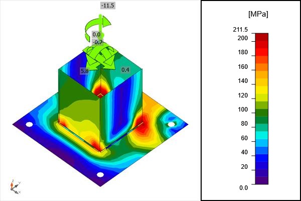
Box column base plate
ROLLER SHUTTER FRAME · AISC 360-16
About this sample
What was removed
Client, location and people are not shown, and software names are replaced with generic terms. Everything else — the structure, the loads, the results and the margins — is as delivered. The whole project, from architectural drawing to shop drawings, is on its case study page. The connections come from other delivered projects; their plots are shown as computed, without client or location.
Who signs it
I prepare the calculation and its documentation. Construction documents are reviewed and signed by a licensed partner engineer.
Need a report like this?
Send a drawing or a model and tell me what has to be checked. I will reply with what I need and what you will get.
info@structomat.com