

From architectural drawings to a designed and detailed entrance canopy
An entrance canopy with a gatehouse underneath and an identical gatehouse beside it. Only architectural drawings existed — no structural system, no member sizes. I built the 3D detailing model first, derived the analysis model from it, designed the members and base plates, and put the plates and anchors back into the detailing model.
Case study
The whole workflow in about a minute and a half (no sound).
Step by step
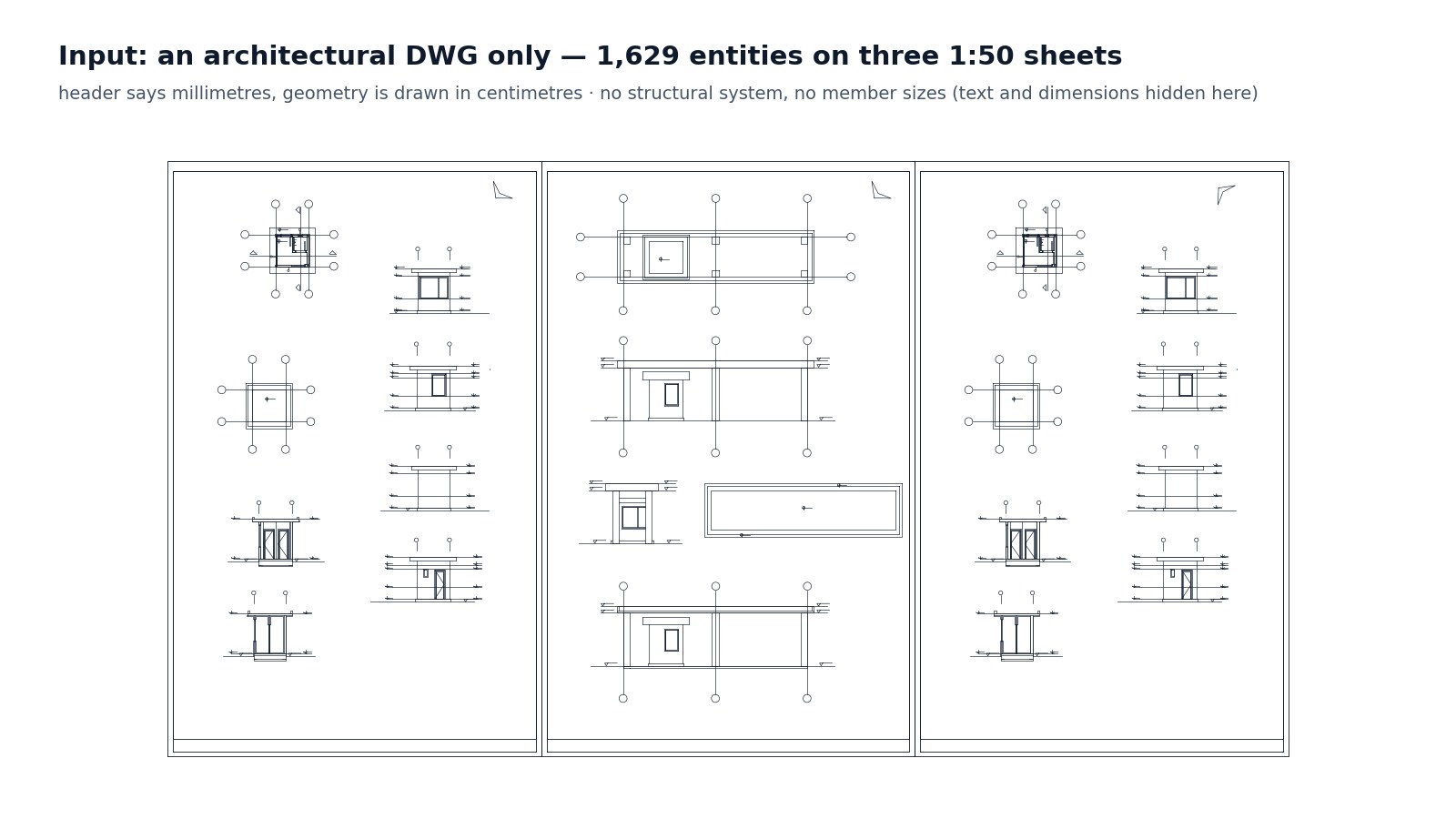
1 · The input: architectural drawings only
The architect’s DWG had three 1:50 sheets with 1,629 entities: a 14.9 × 4.0 m flat-roof canopy with a gravel roof and a parapet, and two identical gatehouses. No structural system, no member sizes. The file header declares millimetres, but the geometry is drawn in centimetres, and the levels in plan, section and elevation did not agree with each other. The engineer chose steel and box sections that fit the architecture, set the roof build-up and confirmed the levels.
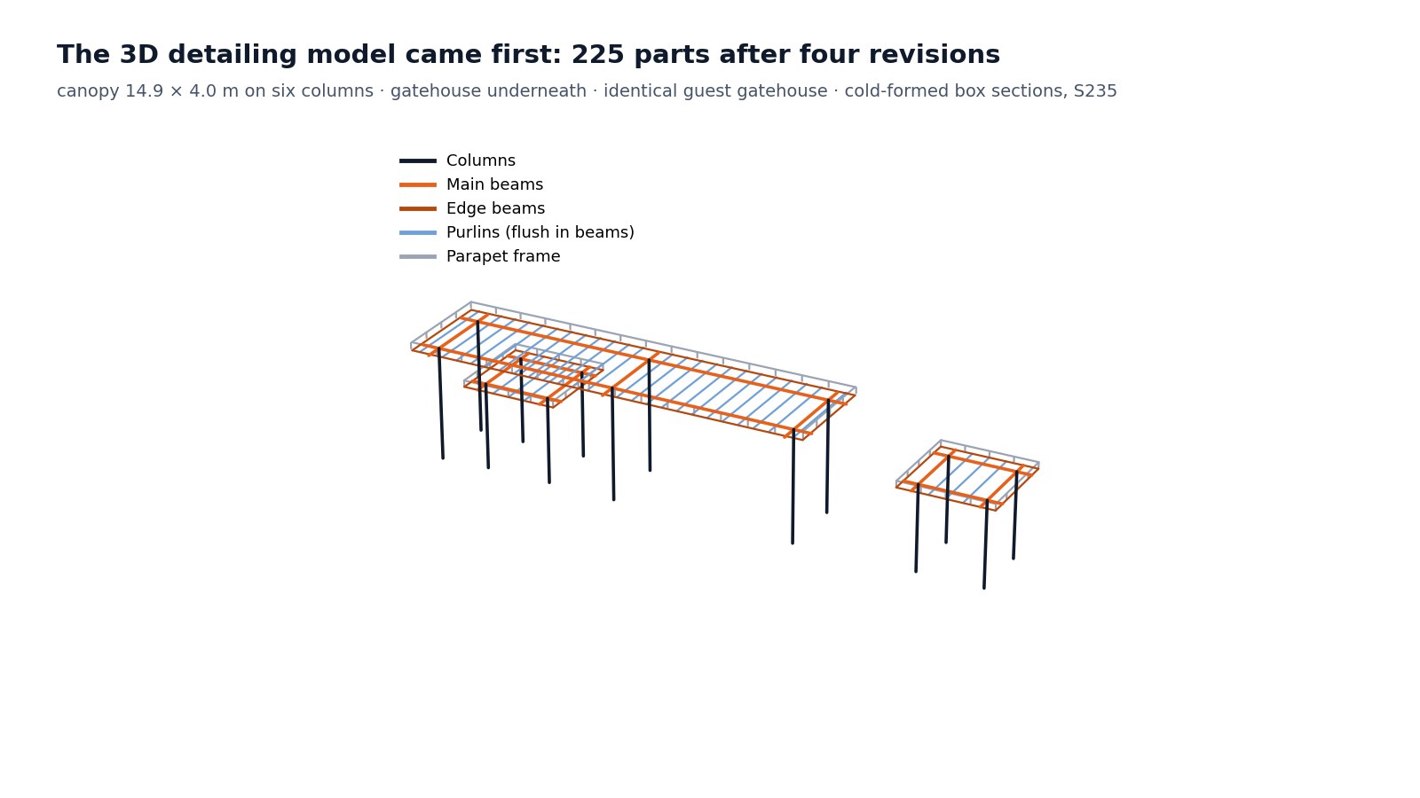
2 · The 3D detailing model came first
I generated the detailing model from a geometry script and revised it four times: the parapet, the gatehouse levels the engineer measured on the elevations, then the grid. The grid lines and the gatehouse outline in the canopy plan sat inside blocks inserted far away from the sheets. My first reading did not look inside blocks and I placed the gatehouse in the wrong position; the engineer caught it from a screenshot. Since then every architectural drawing is read with block contents expanded in place. Purlins sit flush inside the beams so the roof finish reaches the architect’s level. Result: 225 parts.
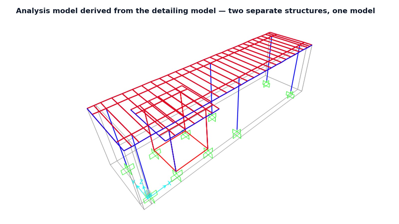
3 · The analysis model, derived — not redrawn
The analysis model was derived from the detailing model. The canopy and the gatehouse under it are separate structures that never touch, and the general geometry step treated their nearby axes as one, shifted them and dropped purlins. For this project I replaced that step with a geometry builder that keeps each structure on its own axes, and compared every support position with the source. 154 nodes, 254 members, 10 fixed supports, 106 load panels, zero negative stiffness eigenvalues. The guest gatehouse is identical and stays out; the parapet members are not modelled, their loads are.
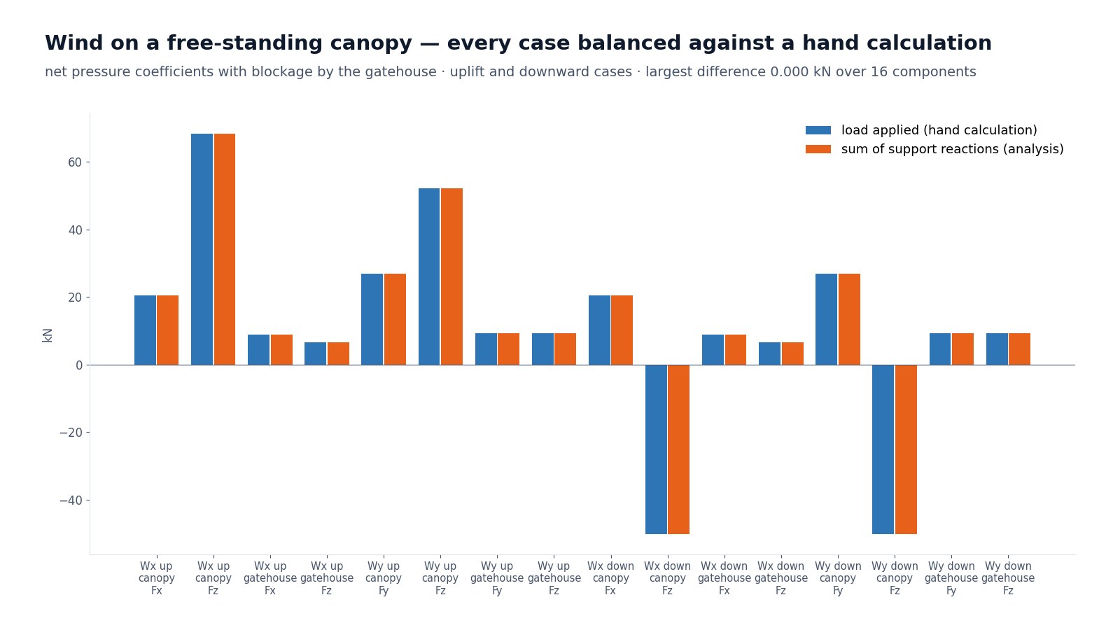
4 · Loads, each one balanced by hand
Gravel roof finish 1.10 kN/m², snow 0.88 kN/m², roof live load 1.0 kN/m², parapet loads on the edge beams. The canopy is a free-standing roof (EN 1991-1-4 §7.3): net pressure coefficients with blockage by the gatehouse, in both uplift and downward cases; the gatehouse is a closed building. For all eight wind cases the applied load equals the sum of support reactions. Along the way I found that the shared load step also put the gravel roof finish on the gatehouse walls; corrected here and logged for the shared code. 125 combinations.
5 · Member design — Direct Analysis Method
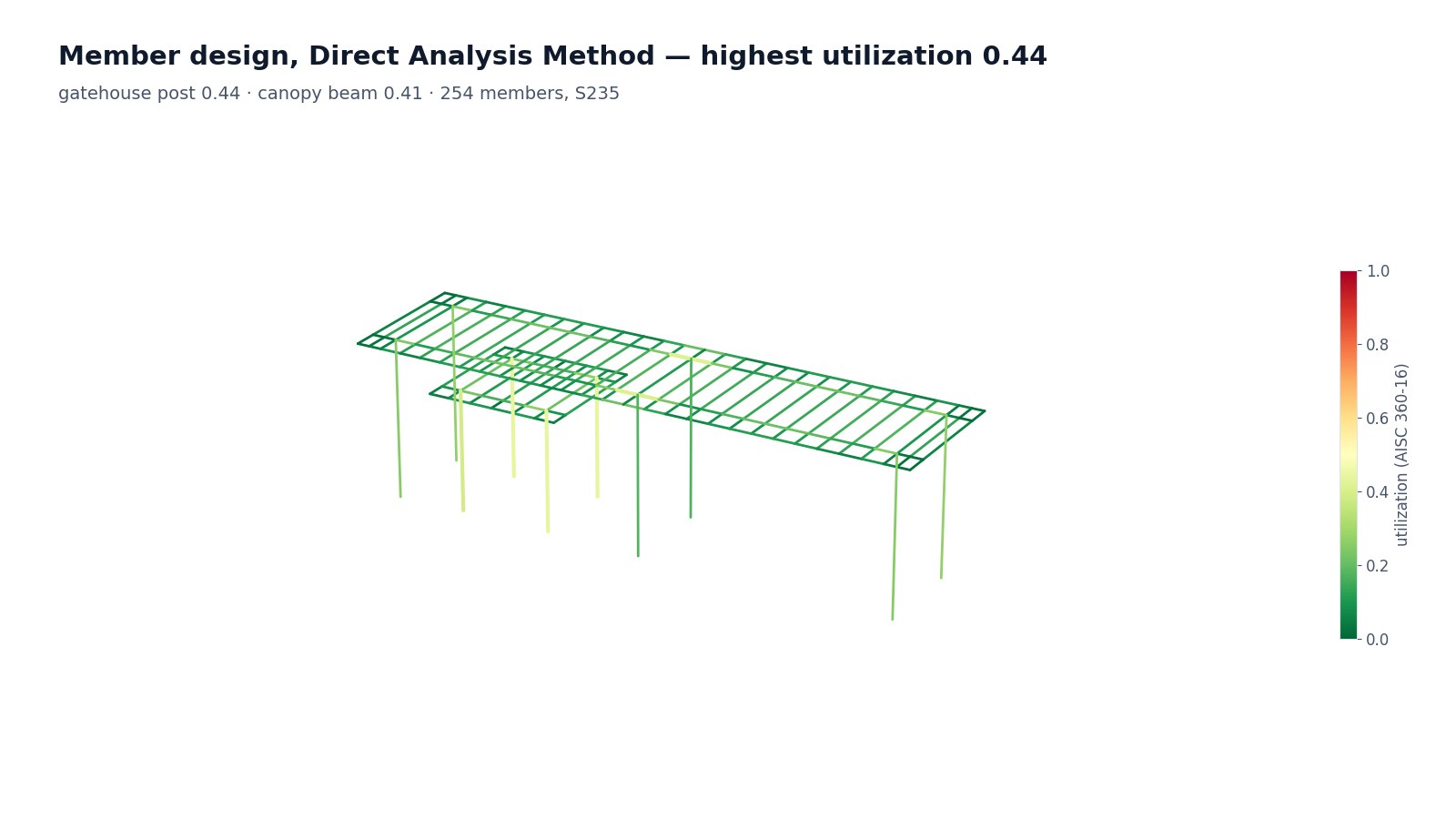
Members are checked to AISC 360-16 with the Direct Analysis Method, using the S235 grade the engineer chose for box sections. Highest utilization: 0.44 on a gatehouse post; the canopy beams reach 0.41 under the downward-wind combination, the canopy columns 0.27.
6 · Serviceability, span by span
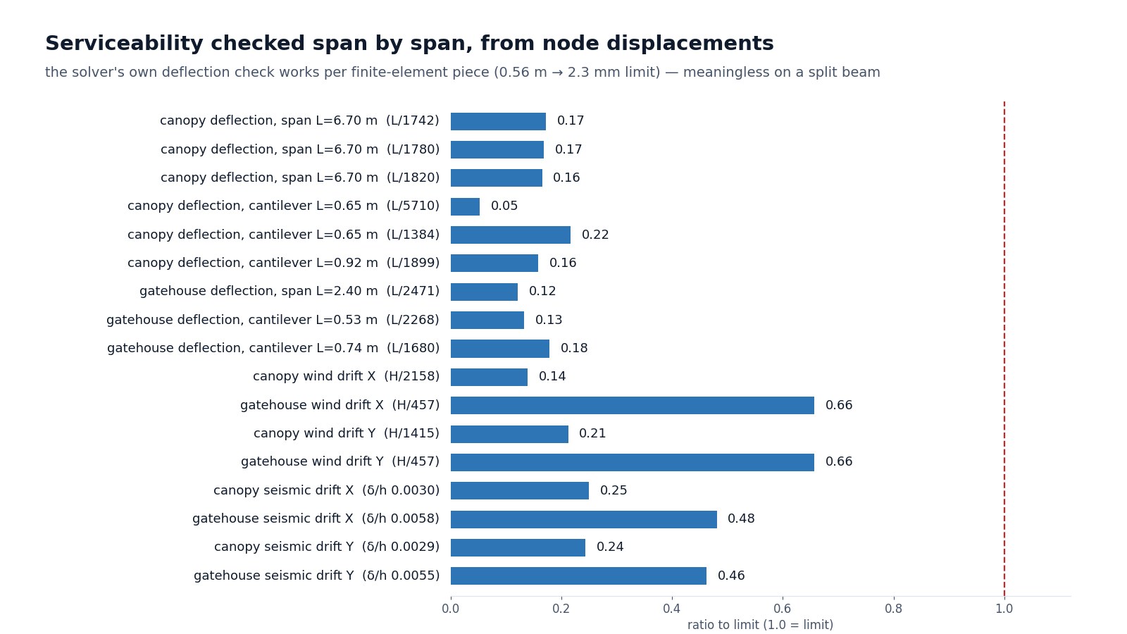
The software’s own deflection check works per finite-element piece: on a beam split at every purlin, a 0.56 m piece gets a 2.3 mm limit — meaningless. I computed deflections span by span from node displacements: canopy beams L/1742, the worst cantilever L/1384. Wind drift of the gatehouse is H/457 against H/300; seismic drift ratios stay at or below 0.0058.
7 · Base plates in connection design software
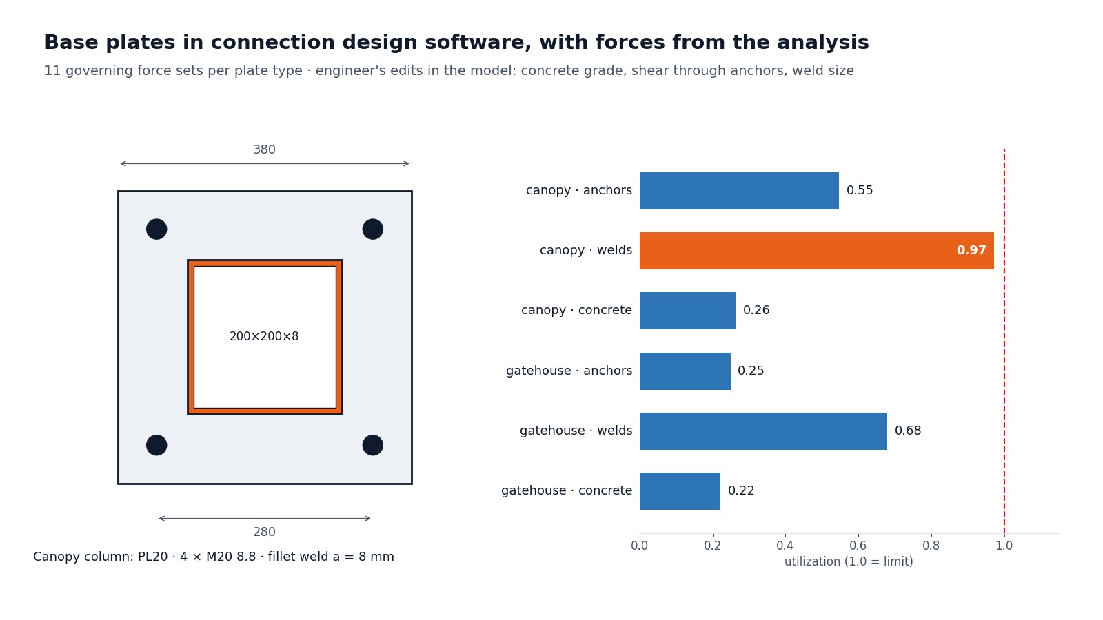
From the analysis I picked 11 governing force sets per plate type — maximum anchor tension, uplift, compression, moment and shear, overstrength combinations included — and built the connection models automatically. The first import did not converge: the recommended welds were not created on import, so the welds are now written explicitly. The engineer then edited the model: concrete C30/37, shear through the anchors, weld size. Canopy plate: anchors 0.55, welds 0.97, concrete 0.26. Gatehouse plate: 0.25 / 0.68 / 0.22.
8 · Back into the detailing model
The checked plates went back into the detailing model: 14 base plates, 56 anchor rods with washers, and the welds; the columns now start on top of the plates. Door and window frames were added (not structural, outside the analysis). General arrangement drawings with profile labels were produced, cleaned up and merged into a single DWG.
9 · The deliverable
The general report template produced sentences that belonged to other projects — a bracing system that does not exist here, a closed-building wind diagram for an open canopy. I wrote a project-specific report instead: 62 calculation pages plus the two base plate reports, 78 pages in total. Construction documents are reviewed and signed by a licensed partner engineer.
In numbers
What stays with people
Decisions
Steel and box sections, the roof build-up and levels, fixed bases, the S235 grade, one model for both structures, the load assumptions and the base plate edits were the engineer’s decisions. I proposed, checked and documented them.
Responsibility
Foundations stay outside this scope. The calculation report going to construction is reviewed and signed by a licensed partner engineer.
Only have architectural drawings?
Send the drawings and a short description. The first step is a structural proposal for the engineer to review.
info@structomat.com