

Bracing node at an HEA 240 column with an IPE 360 beam
Tubular braces and an IPE 360 beam meet at an HEA 240 column through cover plates and an end plate. M20 8.8 bolts.
Connection library · Bracing and gusset nodes
← All connections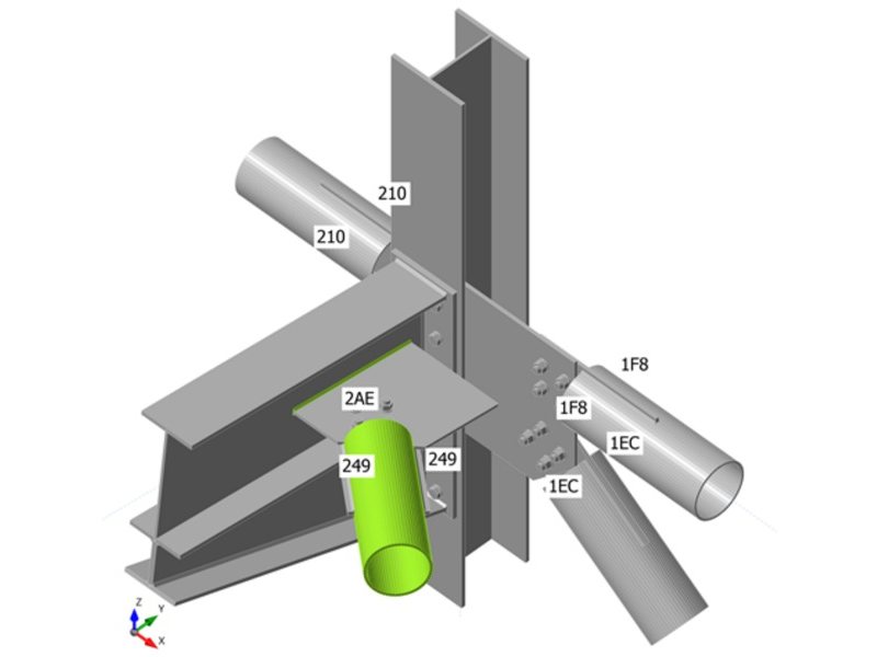
The 3D model is the connection as it was checked: members, plates, welds and bolts. Drag to rotate, scroll or pinch to zoom, tap a part type to hide it.
- Members
- IPE 360 (S275), HEA 240 (S275)
- Plates
- 10–15 mm thick
- Bolts
- M20 8.8
- Welds
- fillet, throat 4–8 mm
- Design code
- AISC 360-16
- Method
- Component-based finite element model (CBFEM)
How it was checked
Every plate, bolt and weld in one model
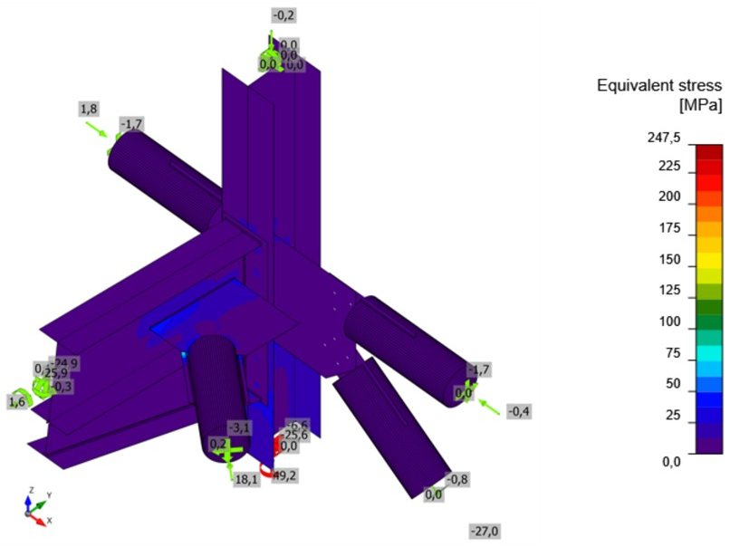
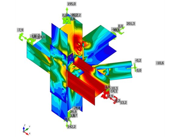
The joint is modelled with shell elements for the plates and member ends, and with nonlinear springs for bolts, welds and anchors (the component-based finite element method). The member forces are applied at the member ends and the model is loaded step by step to the full design load.
Plates pass when the plastic strain stays below the limit of the code; bolts, welds and anchors are checked against the component resistances of AISC 360-16. The bars above show each component’s utilisation for the governing load case.
More bracing and gusset nodes
 Bracing and gusset nodes
Column node with UPN 160 and angle braces on an HEB 200
AISC 360-16 · Bolts 95 % of capacity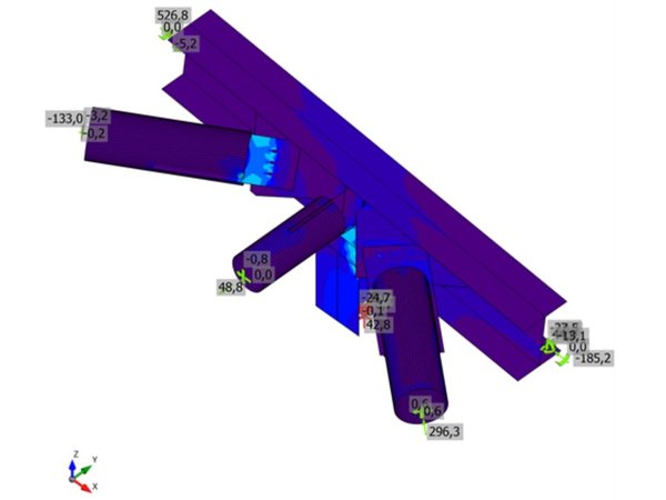 Bracing and gusset nodes
CHS 219.1 braces on an HEB 400 through a gusset plate
AISC 360-16 · Welds 86 % of capacity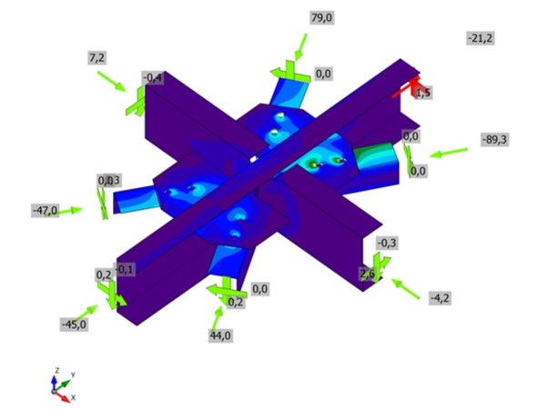 Bracing and gusset nodes
Cross node: UPN 200 members with angle braces
AISC 360-16 · Bolts 83 % of capacity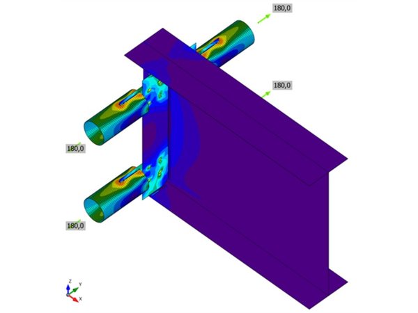 Bracing and gusset nodes
Tubular braces bolted to the web of a deep girder
AISC 360-16 · Welds 76 % of capacityNeed a connection like this designed?
Send the member sizes and forces, or the analysis model. You get the checked connection with its report and detail sketches.
info@structomat.com You get a written scope and price before any work starts.