

Steel approval drawings and submittal packages, ready for review.
Before steel is fabricated, the engineer of record and the general contractor review and approve the shop drawings. I prepare the whole package: erection drawings, anchor rod plan, shop drawings, connection calculations where the connection design is part of the job, a transmittal, a drawing log and an RFI log. When the comments come back, they go into the model and the set is reissued as a clouded revision.
Steel detailing · approval documents
What goes in the package
Everything the reviewer needs in one issue.
| Erection drawings | Plans and elevations with one piece mark per member, top of steel and top of concrete, and the erection notes the crew needs. |
|---|---|
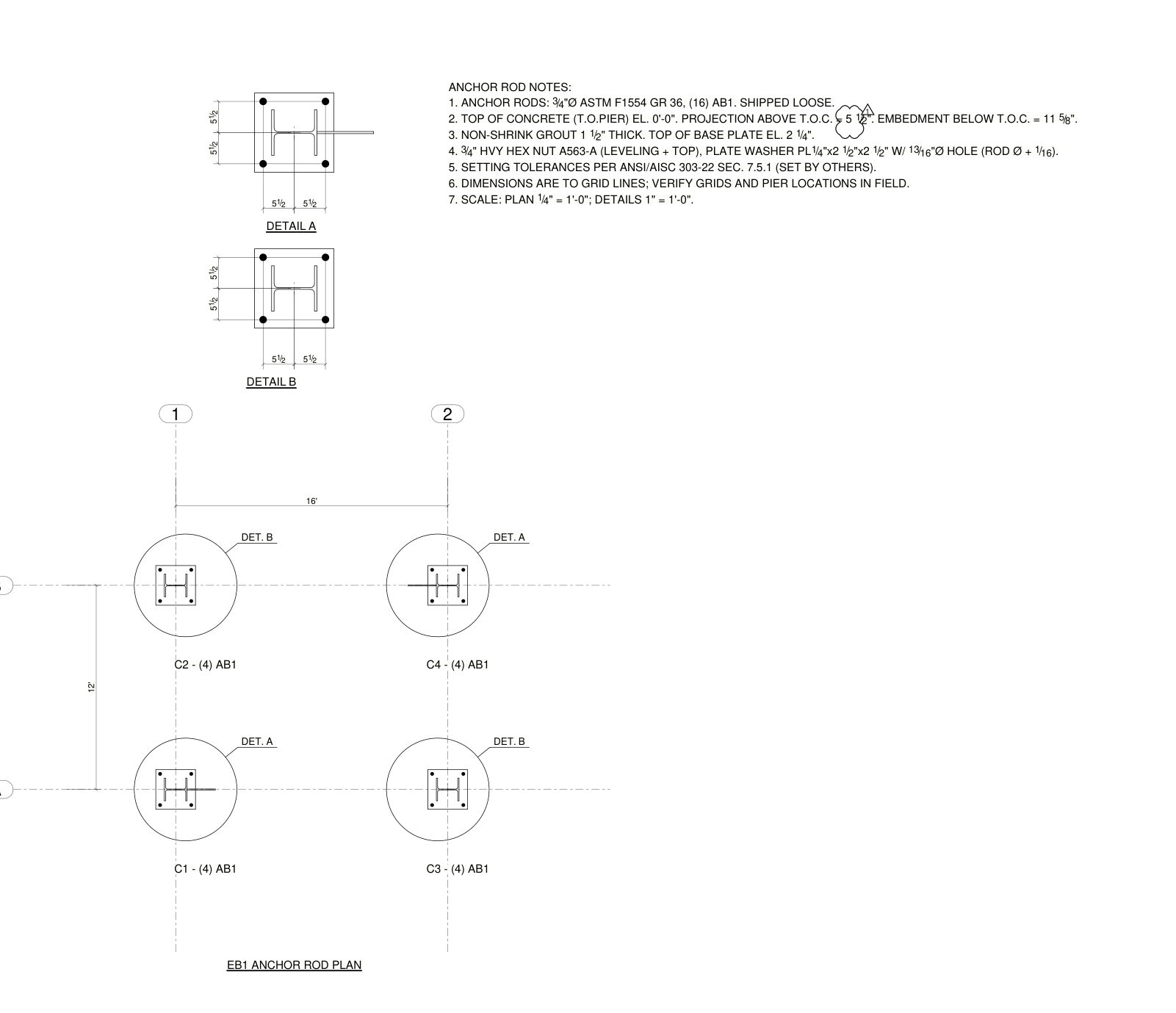
| Anchor rod plan | Grid dimensions, base plate details and what the concrete contractor needs: projection, embedment, grout, nuts and washers. |
| Shop drawings | Assembly and single-part drawings with every fitting located by a dimension, weld symbols, hole sizes and a bill of material. |
| Connection calculations | Where the connection design is part of the job: finite element check reports for plates, bolts, welds and anchors, with the governing load combination. |
| Transmittal | What is sent, to whom and why: for approval, for information, or for fabrication. |
| Drawing log | Every sheet with its title, revision and date, so nothing is reviewed against an old sheet. |
| RFI log | Every question to the engineer of record or the architect, with the assumption used until it is answered. |
| Revisions | Comments go back into the model; changed areas are clouded and the revision is recorded on each sheet. |
The approval cycle
From the first issue to released for fabrication.
Model and check
The 3D fabrication model is built from the design drawings; questions go into the RFI log, not into guesses.
Issue for approval
Drawings, calculations, transmittal and drawing log go out together, checked three ways first.
Comments back
Approved, approved subject to corrections noted, or revise and resubmit: each comment goes into the model.
Revise and reissue
The changes are clouded as a new revision, the logs are updated and the set is reissued: for approval again, or, once approved, for fabrication.
By region · United States
What the US standards ask of the package, and how my drawings answer.
Read from the published texts: AISC 303-22 Code of Standard Practice, AISC 360-16 Specification and AWS D1.1:2015. A starting checklist, not a substitute for the project specification: the contract documents and the applicable building code govern, and a project may call for other editions.
| Standard | What the standard says | On my drawings |
|---|---|---|
| AISC 303-22, Section 4.4 | Approval documents go to the owner's designated representatives for design and for construction and are returned to the fabricator within 14 calendar days; the contract documents may set a different period (Section 1.1 and Commentary). Each is annotated approved or approved subject to corrections noted; when required, the corrections are made and corrected documents furnished. Documents not approved are revised and resubmitted (Commentary). | The package goes out with a transmittal and a drawing log; the comments come back into the model, not onto a PDF. |
| AISC 303-22, Section 4.2.3 | Each shop and erection drawing keeps the same number for the whole project and is identified by revision number and date, with each revision clearly identified. | Sheet numbers never change; every revision has a number, a date and a cloud. |
| AISC 303-22, Section 4.4.1 | Approval does not relieve the fabricator of responsibility for the accuracy of the detailed dimensions or the fit-up of parts assembled in the field. | Every bolt hole is measured against the edge distance and spacing limits before issue, and an erector check places every piece from the sheets alone. |
| AISC 303-22, Section 3.2.3 | The owner's designated representative for design (usually the engineer of record) assigns each connection one of three options: Option 1, designed in full on the design documents; Option 2, selected or completed by an experienced steel detailer from the reference information given; Option 3, designed by a licensed engineer working for the fabricator. For Option 3, representative samples of the substantiating connection information go to the engineer of record early for written confirmation, and the engineer in responsible charge confirms in writing that the approval documents incorporate the connection designs. All three options go through the Section 4.4 approval. | Option 1 and 2 connections are detailed from the design documents. Option 3 needs a licensed engineer in responsible charge of the connection design: your own, or a licensed partner engineer where one is agreed at the start. I prepare the designs, the calculations and the references between them and the drawings for that engineer. |
| AISC 303-22, Section 4.6 | RFIs are kept as a written record of questions and answers on the contract documents, and are not used to release the design in increments. | Every open question goes into the RFI log with the assumption used until it is answered. |
| AISC 303-22, Section 6.1.1 | The fabricator identifies material by written procedure. Unless its procedures set another system, shop-standard grades are: W, WT, C and MC to ASTM A992; M, S, MT, ST, HP, angles, plates and bars to A572 Grade 50; HSS to A500 Grade C; pipe to A53 Grade B. Any other grade is identified by grade as well as shape. | The material grade is written on the drawings, not left to the shop standard. |
| AISC 303-22, Section 7.5.1 | Anchor rods are set by the owner's representative for construction to embedment drawings approved by both representatives: top of rod within ±1/2 in. (13 mm); horizontal position, anywhere along the projection above the concrete, within 1/4 in. (6 mm) for 3/4 and 7/8 in. rods, 3/8 in. (10 mm) for 1, 1-1/4 and 1-1/2 in., and 1/2 in. (13 mm) for 1-3/4, 2 and 2-1/2 in. | The anchor rod plan locates every rod from the grid and gives the projection, base plate and grout details the concrete contractor needs. |
| AISC 360-16, Section M1 | Shop and erection drawings distinguish clearly between shop and field welds and bolts, and identify pretensioned and slip-critical high-strength bolted connections. | Field welds are marked as field welds and kept apart from shop welds; where a field groove weld needs a bevel or backing prepared in the shop, the preparation is detailed on the shop drawing. Bolt installation (snug-tight, pretensioned or slip-critical) is stated on the sheets. |
| AISC 360-16, Sections J3.3 to J3.5 | Bolt spacing at least 2-2/3 d (3d preferred), with at least d clear between holes; edge distance at least Table J3.4, plus the C2 increment for oversized or slotted holes (less than d only with the engineer of record's approval); maximum edge distance 12 times the part thickness, not more than 6 in. (150 mm); maximum longitudinal spacing in plates and shapes in contact 24t or 12 in. (300 mm), 14t or 7 in. (180 mm) for unpainted weathering steel. | Checked on every hole of every connected part; the published US sample measured 80 edge distances, none below. |
| AWS D1.1:2015, Sections 2.3.1, 2.3.3 and 2.3.5 | Shop drawings distinguish shop and field welds; show groove weld details, base-metal preparation and backing width and thickness by welding symbols or sketches, with the groove depth S for PJP welds; give the leg size of fillet welds between surfaces at 80 to 100 degrees and the detailed arrangement for skewed joints; show end returns and any required assembly or welding sequence. | Fillet welds are dimensioned by leg size in AWS symbols, never by throat. |
By region · Australia
What the Australian standards ask of the drawings, and how mine answer.
Read from the published texts: AS 4100:2020, AS/NZS 5131:2016 and AS/NZS 1554.1:2014. A starting checklist, not a substitute for the construction specification: the specification and the applicable building code govern, and a project may call for other editions.
| Standard | What the standard says | On my drawings |
|---|---|---|
| AS 4100:2020, Clause 1.6 | The drawings show the design data (design Standards with their date, nominal loads, corrosion protection and fire-resistance level where applicable, steel grades) and, on the drawings or in the construction specification, the design details, including member sizes, the number, size and category of bolts, the size, type, strength and category of welds with the level of examination, the sizes of connection components and the construction category. | Steel grades, bolt sizes and categories, and weld size and category are in the notes on the sheets; the design data comes from the engineer's drawings. |
| AS 4100:2020, Clause 1.7.2 | Four construction categories, CC1 to CC4, in increasing strictness, nominated in the construction specification; if none is nominated, CC2 applies. The fabrication and erection requirements for each category are in AS/NZS 5131. | The construction category is stated in the sheet notes; the published sample states CC2, to be confirmed against the specification. |
| AS/NZS 5131:2016, Clause 4.4.2 | Shop detailing documentation shows, for every assembly, component and connection: identification, steel type and grade, dimensions, camber, location, type and size of welds or bolts, weld and bolting categories, orientation, temporary connections, surface preparation and coating, lifting points, set-out from the project grid, and marking plans including holding-down bolts, to the AS 1100 series. | Marking plans for the roof and walls, a holding-down bolt plan with a schedule, and every piece located from the grid. |
| AS/NZS 5131:2016, Clause 4.4.3 | The documentation transfers the construction specification accurately and gives dimensions for accurate fit-up. Each drawing carries a number traceable for the whole job; revisions are uniquely identified and dated with their scope; where RFIs are issued, a written record of questions and answers is kept. | Each sheet is identified by its drawing number and listed in the drawing list; piece marks run from 1 with no gaps. Every sheet has a revision block for the number, date and description of each revision, and open questions go into an RFI log with the assumption used. The published sample is a first issue: its revision blocks are still empty, and its RFI log lists the nine items the sheets mark TBC or HOLD. |
| AS/NZS 5131:2016, Clause 4.4.4 | The construction specification nominates the competent person who reviews and approves the shop detail documentation, which is annotated either approved or approved subject to corrections noted. | The set goes for approval with a drawing list and a transmittal; the reviewer's comments are made in the model and the sheets regenerated, not marked up on the PDF. The published sample, issued for information, includes both. |
| AS 4100:2020, Clause 9.2.1 and 9.2.3.2 | Bolting categories: 4.6/S and 8.8/S snug tight; 8.8/TB and 8.8/TF fully tensioned. A connection in category 8.8/TF or 10.9/TF is identified as such, and the drawings show the surface treatment it needs and whether the contact surfaces are masked during painting. | The bolting category is on the sheets: in the sample, M20 8.8/TB at the knees and apex, M16 8.8/S bracing and M12 4.6/S purlins and girts. |
| AS/NZS 1554.1:2014, Clauses 1.6 and 3.1.3 | Welds are category GP (general purpose) or SP (structural purpose). Drawings of welded connections give the parent metal grade, the weld metal strength, the location, type, size and effective length of welds, whether shop or site, the weld category, any non-standard or seal welds, the type and extent of inspection and the design Standard. | Weld size, category and the design Standard are in the sheet notes (the sample: 6 mm continuous fillet welds, category GP, unless noted). The weld metal strength and the type and extent of inspection come from the construction specification and are added to the notes; the illustrative sample leaves them to the engineer. |
| AS 4100:2020, Clause 9.5 | Minimum pitch 2.5 df. Minimum edge distance 1.75 df for sheared or hand flame cut edges, 1.50 df for machine cut, sawn or planed edges, 1.25 df for rolled edges. Maximum pitch the lesser of 15 tp or 200 mm (other limits for some cases); maximum edge distance 12 tp, not more than 150 mm. Holes to AS/NZS 5131. | Checked in the 3D model on every bolt position and every connected part: in the published sample, 1300 bolt positions and 2276 edge distances, none below minimum. |
| AS/NZS 5131:2016, Clauses 6.7.2 to 6.7.4 | For members designed to AS 4100, bolt holes 2 mm larger than the bolt up to 24 mm and not more than 3 mm larger above (members designed to AS/NZS 4600: 1 mm up to 12 mm, not more than 2 mm above). Base plate holes not more than 6 mm larger than the anchor bolt; from 3 mm larger, a plate washer at least 4 mm thick under the nut, covering the hole with an edge distance of half the hole diameter. Oversize holes not more than the greater of 1.25 df or df + 8 mm, used in tensioned connections with hardened or plate washers under both the head and the nut. | Hole sizes are stated on the sheets: D+2 unless noted; M24 holding-down bolts in 30 mm base plate holes under 8 mm plate washers. The sample's purlin and girt bolts (M12 4.6/S) are in 18 mm holes, the cold-rolled supplier's detail; that is an oversize hole under Clause 6.7.3, and on a live job it goes to the engineer for acceptance. |
| AS/NZS 5131:2016, Clause 11.7 | Erection drawings show plans and elevations with the erection mark of every member, grid locations and support positions with their tolerances; footing plans give footing and base plate locations and levels, orientation and datum; footing drawings give the anchor bolt details, packing or shimming and grout; components or assemblies over 5 t carry their weight, and large or irregular items their centre of gravity. | The holding-down bolt plan and the erection drawings give the grid, base plate details and the rod, washer and grout schedule the concreter sets out from. |
Evidence
Sample packages you can open.
A US submittal, checked three ways
14 sheets, 80 edge distances measured, three clouded revisionsOpen →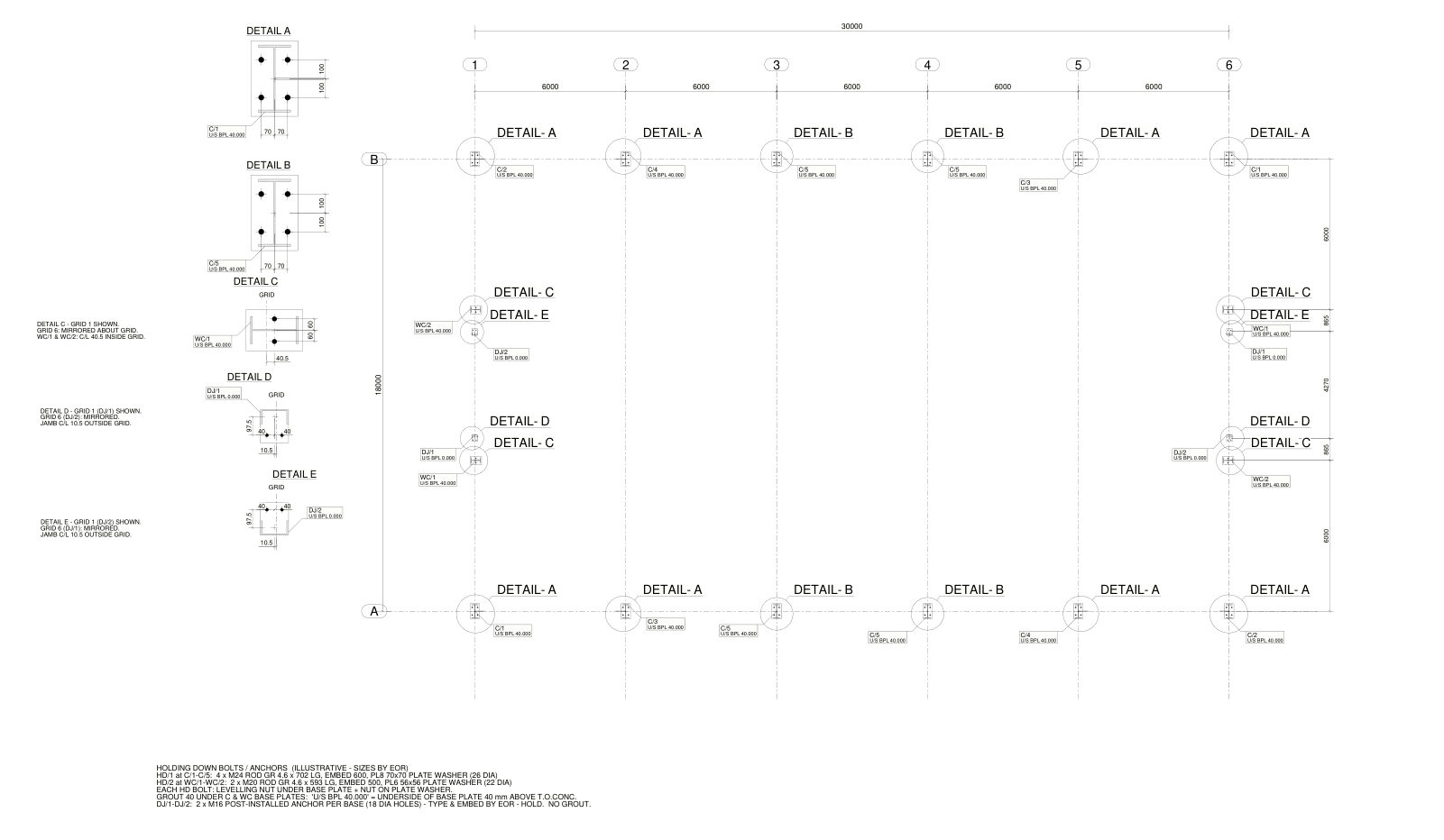
An Australian portal frame set
Holding-down bolt plan, erection and shop drawings to AS 4100Open →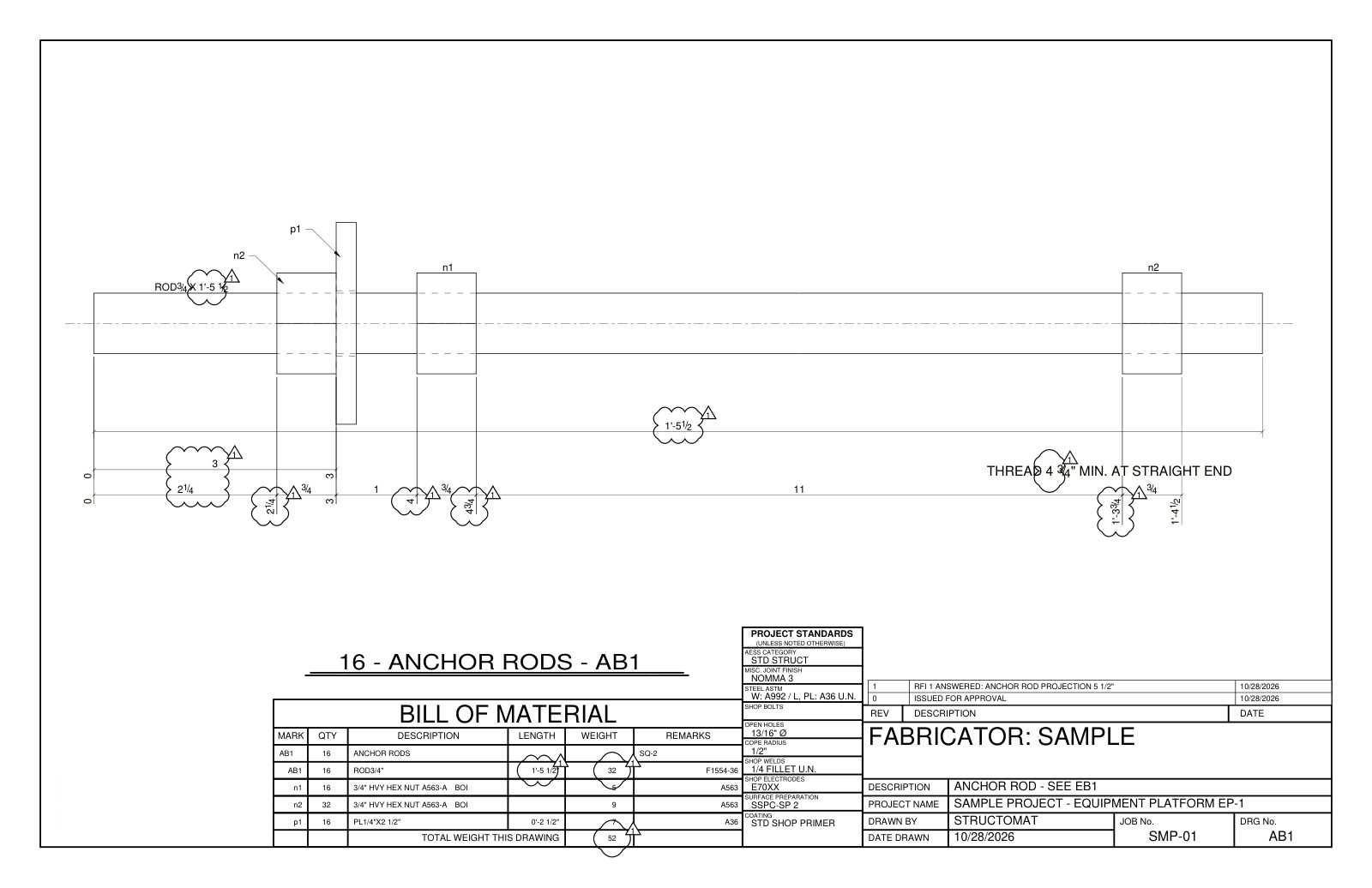
A clouded revision after review comments
Comments back into the model, changes clouded on the sheetsOpen →Part of a bigger job? Approval documents can come with any outsourced shop drawing package.
FAQ
Questions about approval drawings
What is in a steel submittal package?
The drawings the reviewer approves (erection drawings, anchor rod plan and shop drawings), with a transmittal that lists what is sent and why, a drawing log with every sheet and its revision, and an RFI log with the open questions. Where the connection design is part of the job, the connection calculations go with it.
What happens when the drawings come back with comments?
Each comment goes back into the 3D fabrication model, the sheets are regenerated and the changes are clouded with a new revision, then the set is issued again. Drawings are never patched by hand.
Can you do the connection design for the submittal?
Yes. Connections are designed and checked with the finite element method using the forces from the design drawings, and the check reports go into the package. Where the contract delegates connection design to the fabricator's engineer (AISC 303 Option 3), the design is carried out under a licensed engineer in responsible charge: your own, or a licensed partner engineer agreed at the start. If the project needs an engineer licensed in a particular state, say so at the start and the route is agreed together.
Do you work in imperial units and to AISC?
Yes: imperial units to 1/16", AWS weld symbols and AISC detailing practice. A complete sample submittal is on the US shop drawings page. For Australian work the set follows AS 4100, AS/NZS 5131 and AS/NZS 1554.1, and for European work the drawings carry the EN 1090 execution class.
How are the drawings checked before they are submitted?
Three ways: automated checks on the model and the sheets (bolt edge distances and spacing, clashes, hole sizes, unlocated pieces), a separate AI checking agent that reads the set the way a fabricator and an erector would, and an engineer's review.
Have drawings to get approved?
Send the design drawings or the model with the deadline. You get a written scope and a fixed price within 24 hours.
info@structomat.com Your first job is $100. Nothing is paid before you have seen the preview.