

US shop drawings that pass a checking gate before you see them
A complete AISC submittal for a sample equipment platform: anchor rod plan, erection drawings, shop drawings, RFI log and a clouded revision. Every set I issue goes through the same automated checks. The first draft of this one failed them, and this page shows what the checks caught.
Steel detailing · AISC · sample submittal
The sheets
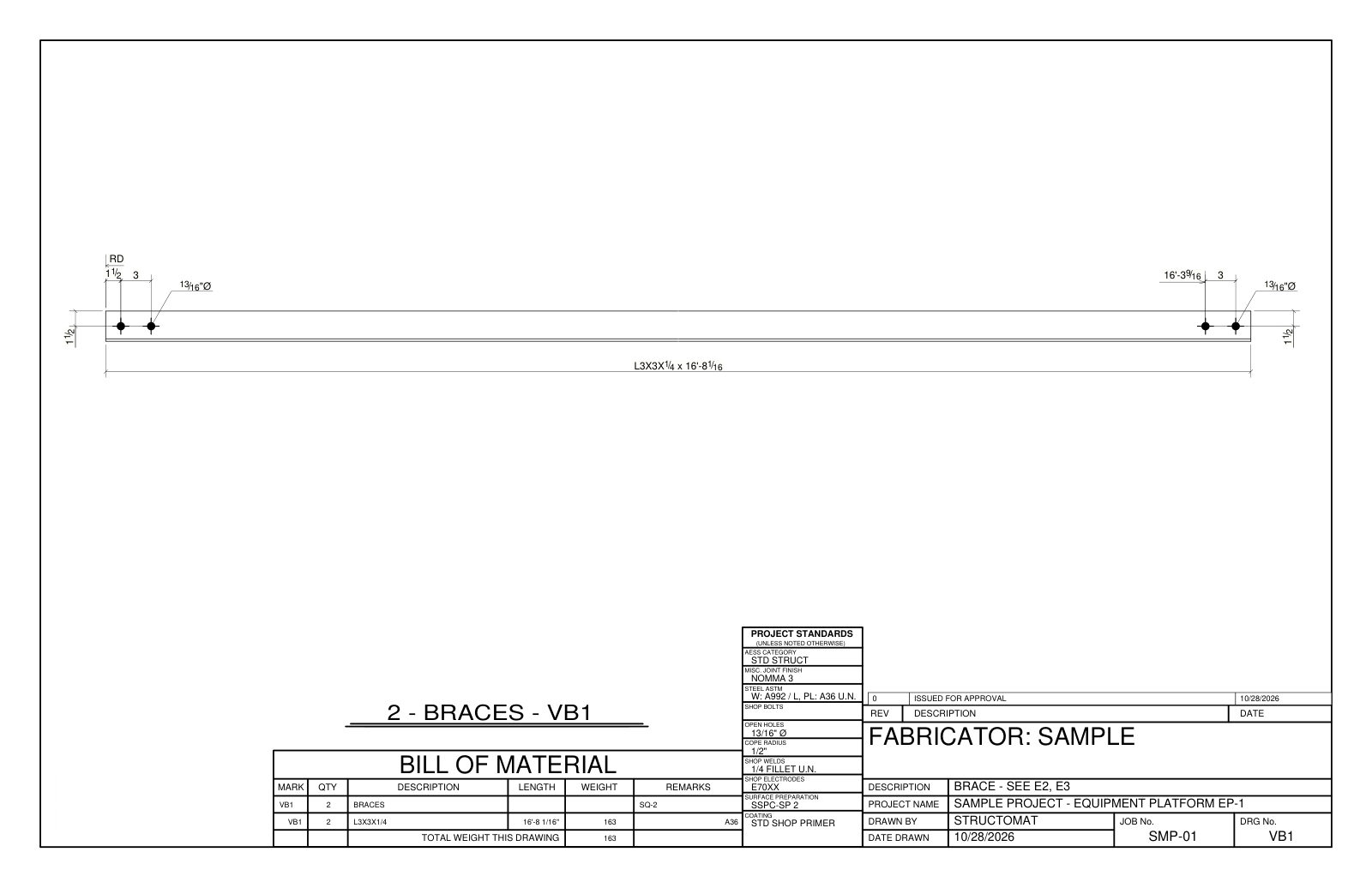
Imperial units to 1/16″, AWS weld symbols, piece marks on the end the shop stamps, standard holes noted on every bolt group, and a bill of material on each sheet. Member sizes in this sample are illustrative; on a real job they come from the Engineer of Record’s design drawings.
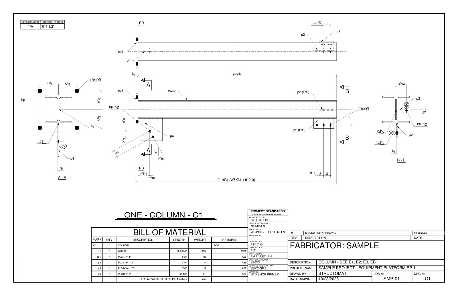
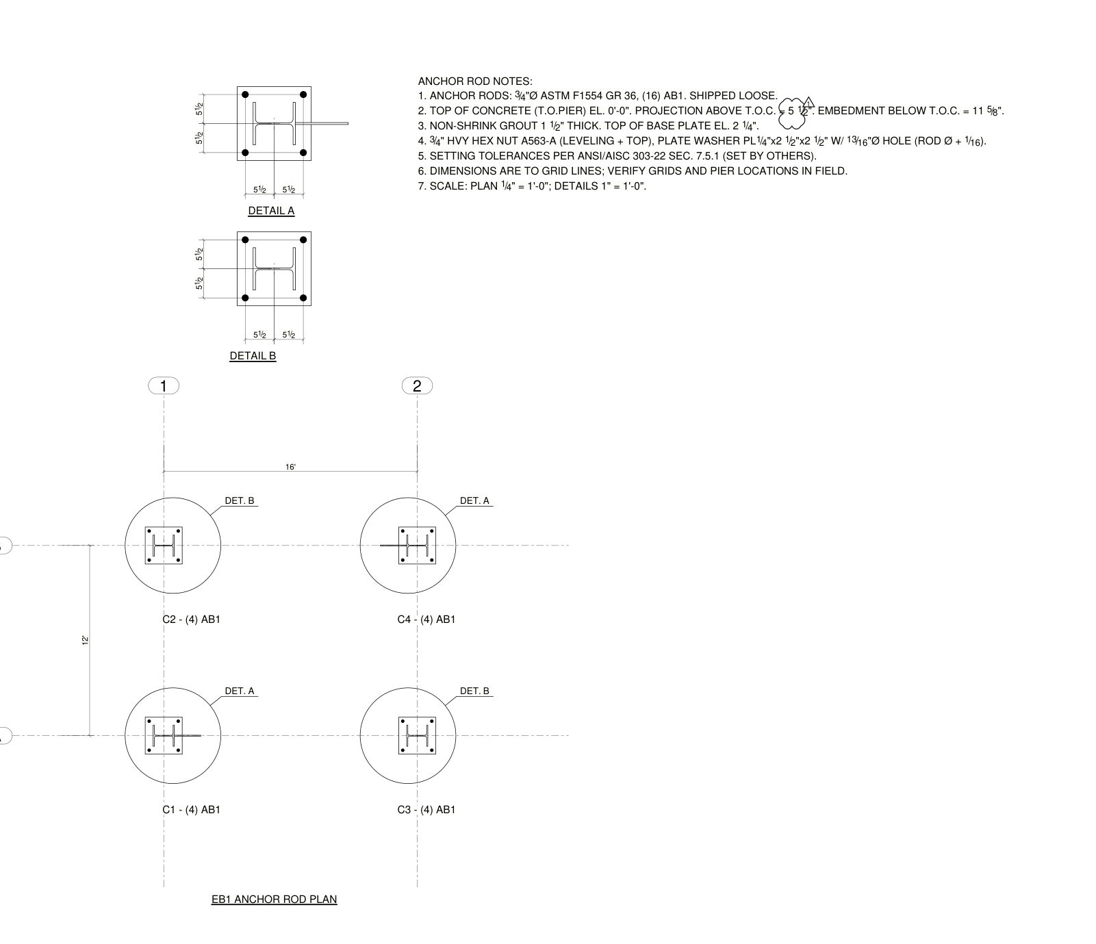
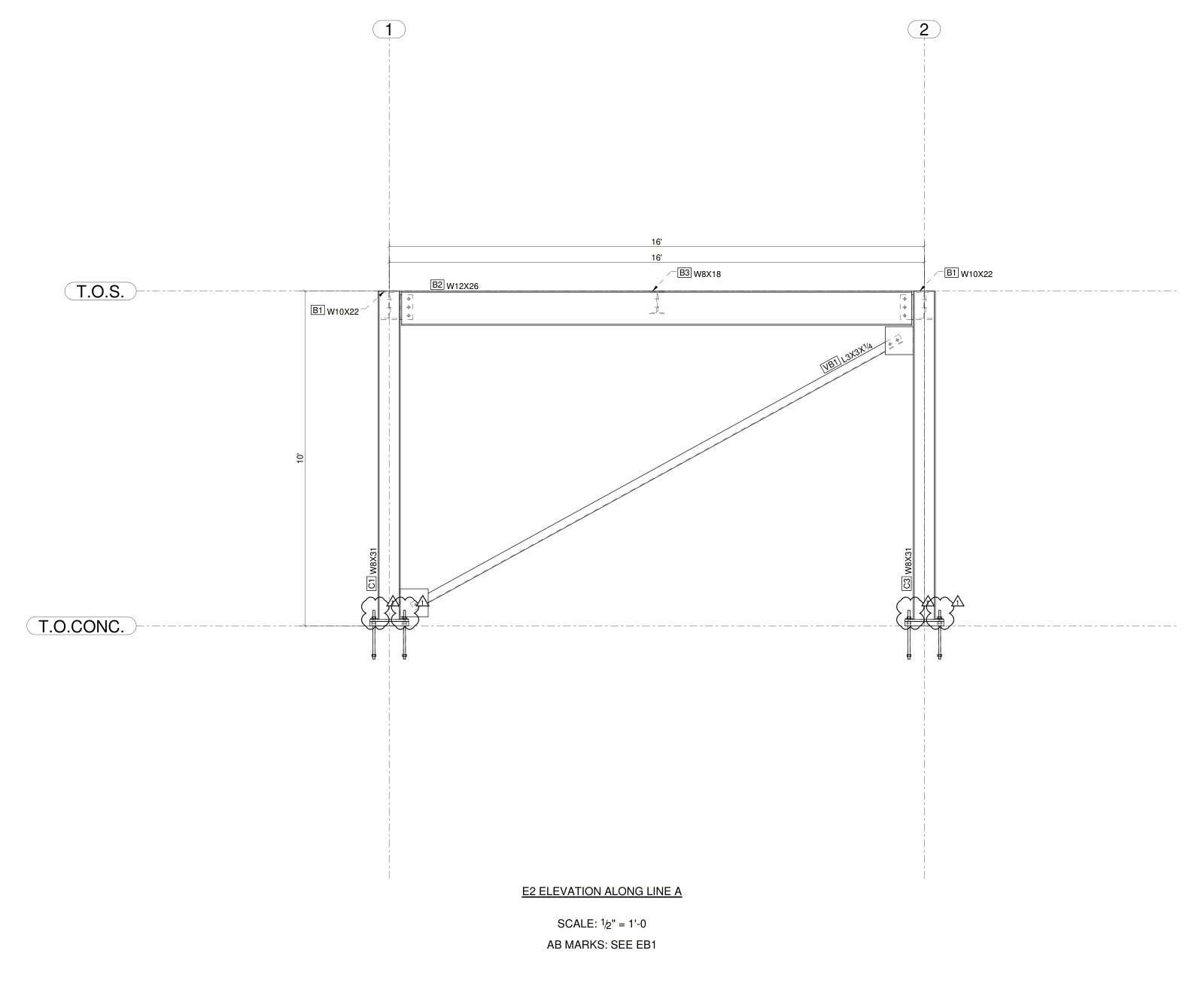
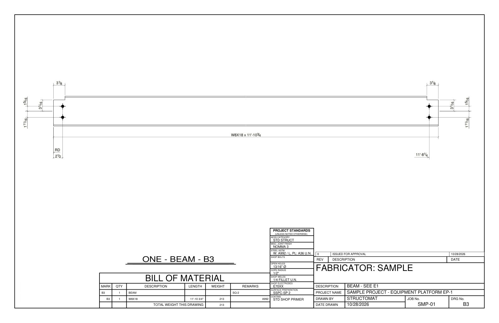
The checking gate
The 3D fabrication model and every sheet are checked before the set is released. An error stops the set; it is fixed in the model and the sheets are regenerated, never patched by hand.
| Check | Basis | This set |
|---|---|---|
| Bolt edge distance, every hole in every connected part | AISC 360-16 Table J3.4; below 1d needs EOR approval | 80 measured, 0 below |
| Bolt spacing, including holes from different connections in one part | AISC 360-16 J3.3 (2⅔ d, 3d preferred) | 0 below |
| Maximum edge distance on plates | AISC 360-16 J3.5 (12t, 6 in.) | 0 over |
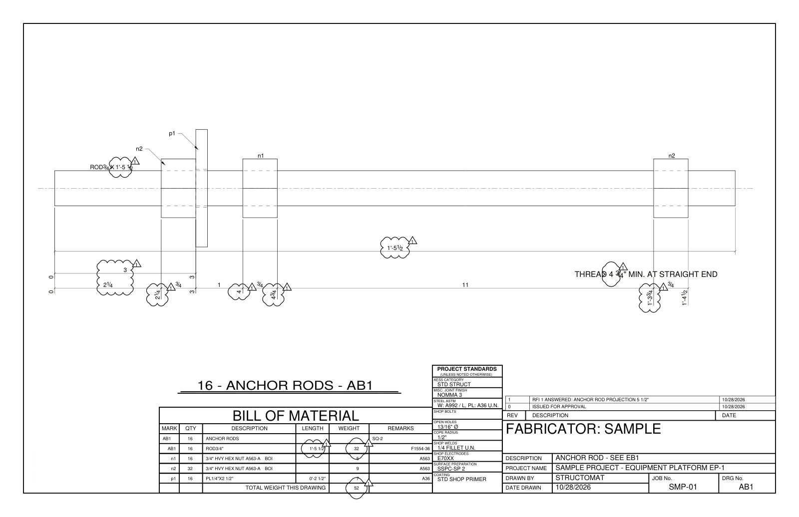
| Standard holes | d + 1/16″ | all 13/16″ for 3/4″ bolts |
| Clashes between solids, existing structure treated as an error | 3D model | 0 |
| Erector check: every piece on a shop drawing located by a dimension | simulated fit-up from the sheet alone | 18 / 18 pieces placed |
| Field welds kept off shop drawings | shop vs. field weld in the model | 0 |
| One piece mark for identical pieces; shipping marks upper case, assembly marks lower case | AISC detailing practice | pass |
| Fractions to 1/16″, no leading zeros | AISC detailing practice | pass |
| Marks overlapping marks or dimensions | sheet geometry | 0 |
Added after this set was issued: the erectability check. The same model passes every row above and is clash-free, yet three of its eleven lifts cannot get into place when it is erected columns first, then beams, then braces.
My own first draft failed it
These are the errors the gate found in the first version of this sample, before anyone would have seen it. The model accepted each of them without complaint.
Plate washers on the column flange
With anchor rods at ±4-1/2″, the 2-1/2″ plate washers sat on the W8 flange tips. The pattern was opened to ±5-1/2″ on a 14″ base plate.
Shear tab bolts in the wrong direction
The bolts were generated along the tab instead of through the beam web. The edge distance check reported holes 1/8″ from an edge and two bolt groups on top of each other.
Gusset and shear tab not located
The column and girder sheets showed the fittings but gave no dimension to place them. Location dimensions were added to the sheets.
Gusset edge distance over 12t
On a 3/8″ plate, a bolt sat 4.8″ from the nearest edge. The gusset was reduced from 12″ to 10″.
On a real job, a brace crossing the flange of an existing beam was found in a visual review. Contact with existing structure is now an automatic error in the gate, so it cannot pass silently again.
Revisions you can follow
After the set is issued, every change becomes a numbered revision. Each sheet is compared with the issued copy: changed values are clouded with the revision triangle, the revision is added to the title block, and the drawing log lists which sheets moved to the new revision. Sheets that did not change keep their number.
The submittal package
Organised for approval under AISC 303-22: a transmittal with the reviewer’s action boxes, a drawing log, an RFI log with the assumption used for each open question, an advance bill of material with the field bolt list, and the approval documents as one bookmarked PDF. DWG files on named layers and an IFC model come with every set.
- 00 Transmittal · 01 Drawing log · 02 Approval documents (bookmarked) · 03 RFI log · 04 Advance BOM and field bolts
- DWG of each sheet on named layers (steel, bolts, welds, dimensions, marks, notes)
- IFC4 model with piece marks, bolts and grids, for coordination
Sample project for demonstration only; not for construction. DWG files are available on request.
Send your design drawings
Send the structural drawings, or a link to them. I reply within 24 hours with a fixed price, a delivery date and the RFIs I already see. The first job is $100.
info@structomat.com