

Shop drawings for Australian fabricators, checked three ways before release
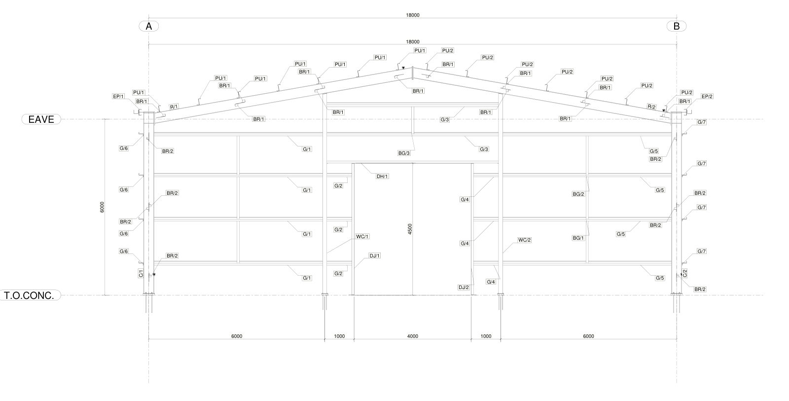
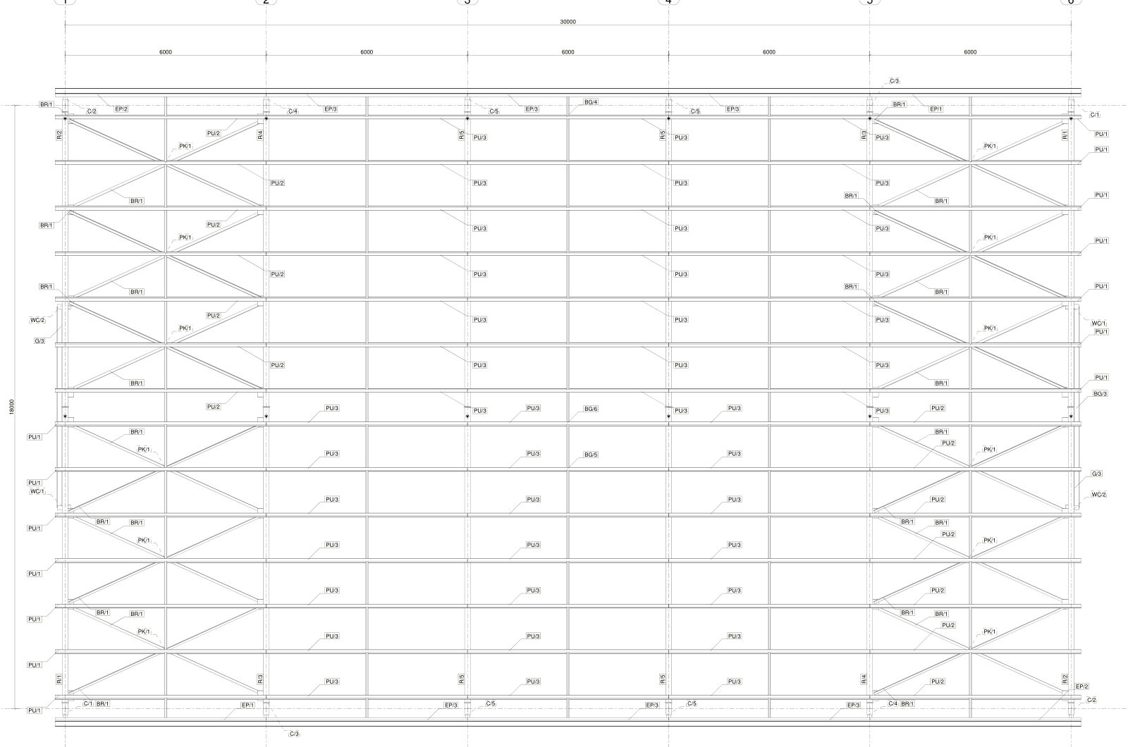
A full sample set for an 18 × 30 m portal frame shed: holding-down bolt plan, erection drawings, shop drawings, cold-rolled order list and NC files, in millimetres with notes to AS 4100, AS/NZS 5131 and AS/NZS 1554.1. Before release the set went through automated checks, two rounds of review by a separate AI checking agent, and a review by a structural engineer of my team. This page shows what the checks found.
Steel detailing · AS 4100 · AS/NZS 5131 · sample set
The sheets
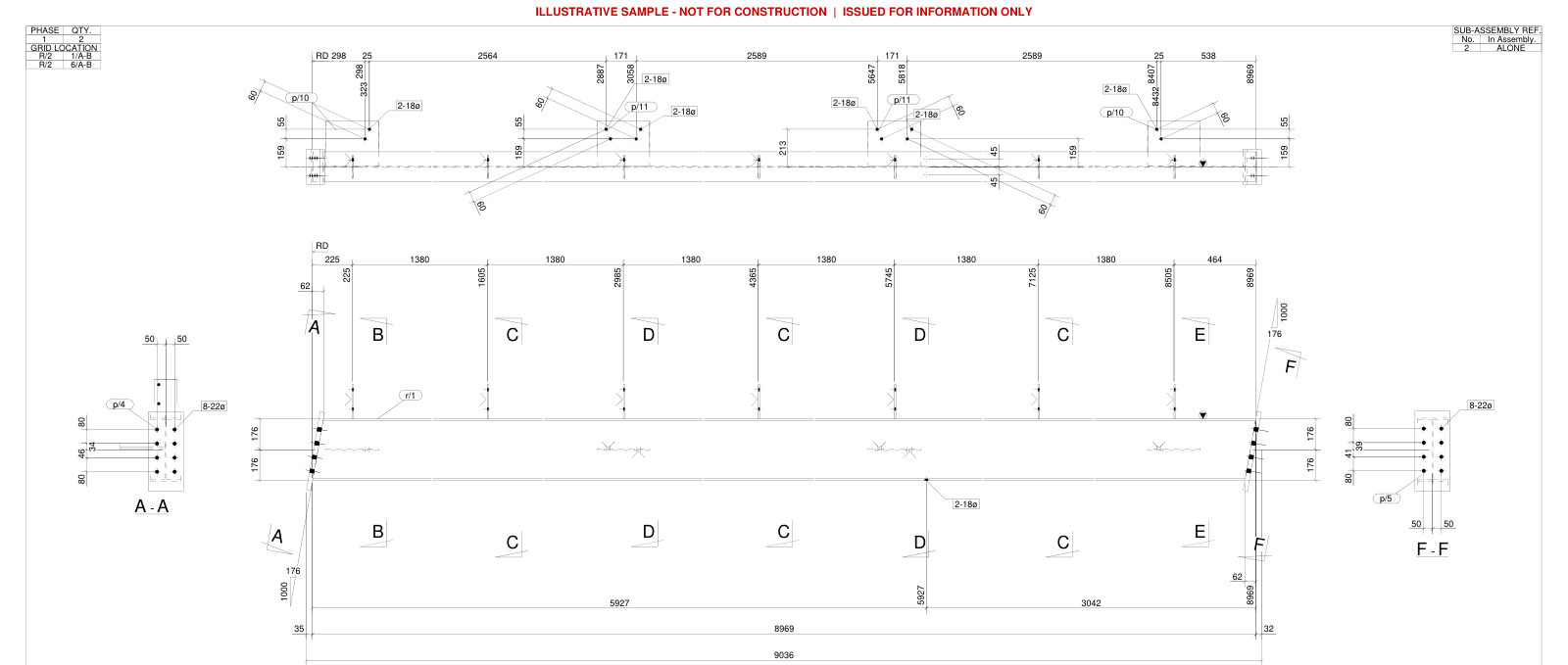
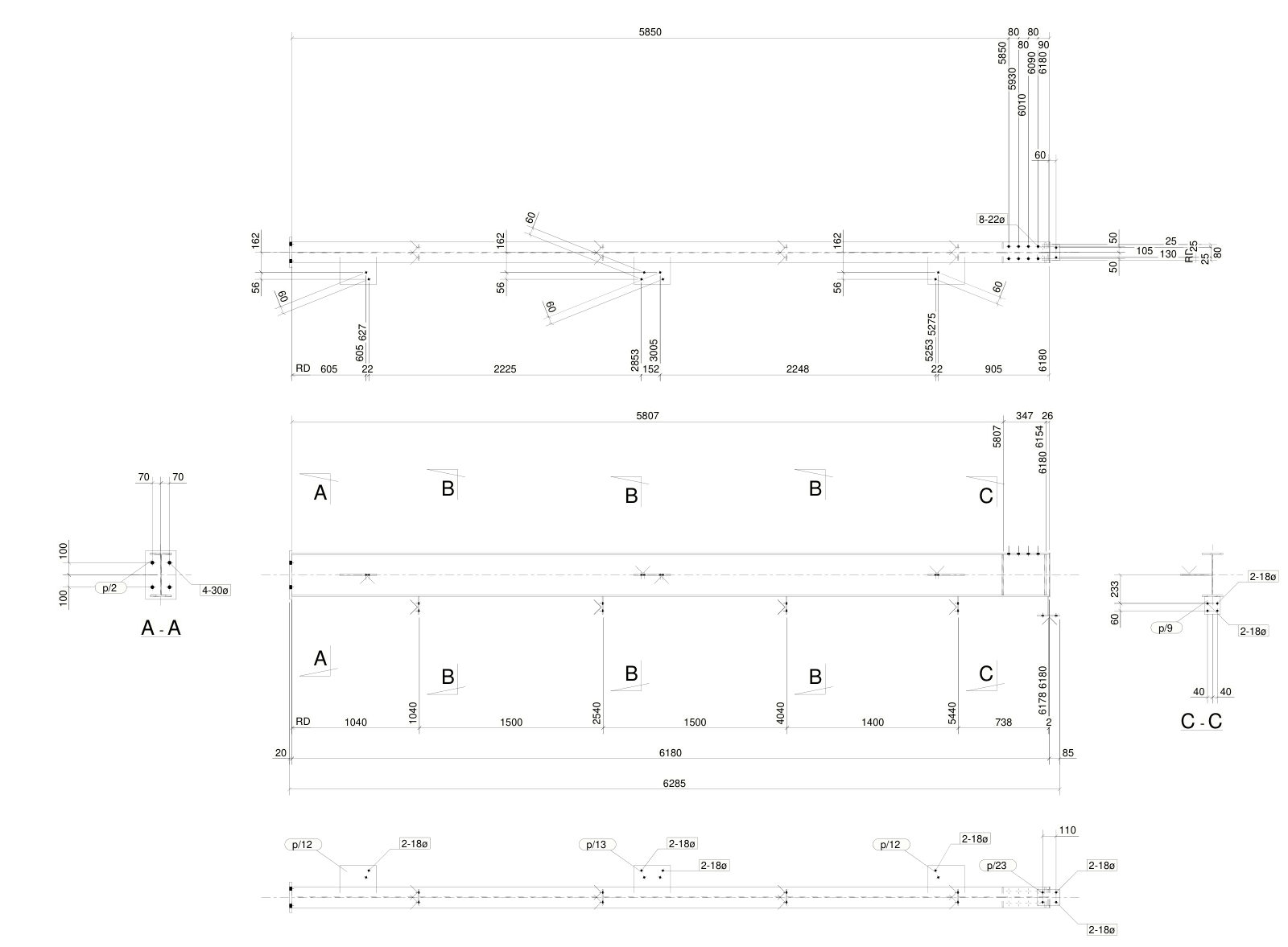
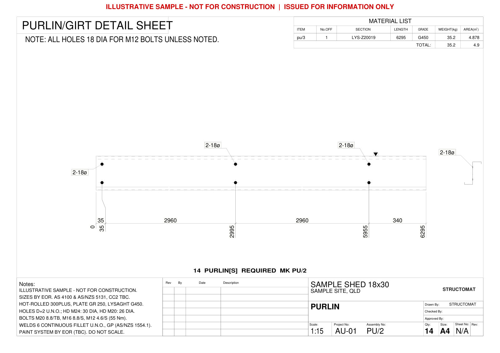
Hot-rolled frames in 300PLUS with grade 250 plate, cold-rolled Z and C sections in G450 with bridging, M20 8.8/TB at the knees and apex, M16 8.8/S bracing, M12 4.6/S purlin and girt bolts. Member sizes in this sample are illustrative; on a real job they come from the engineer’s design drawings.
The checking gate
The 3D fabrication model, the sheets and the NC files are checked before the set is released. An error stops the set; it is fixed in the model or in the sheet generator, and everything is regenerated, never patched by hand.
| Check | Basis | This set |
|---|---|---|
| Bolt edge distance and spacing, every hole in every connected part | AS 4100 minimums | 1300 bolts, 0 below |
| Hole sizes on the sheets, in the notes and in the NC files agree | sheet ↔ NC comparison | 18 mm for M12, consistent |
| Clashes between members | 3D model | 0 |
| Every NC part present once | NC (DSTV) files ↔ model | 678 parts, 0 missing, 0 duplicate |
| Marks numbered from 1 with no gaps; left- and right-hand pieces kept as separate marks | model numbering | pass |
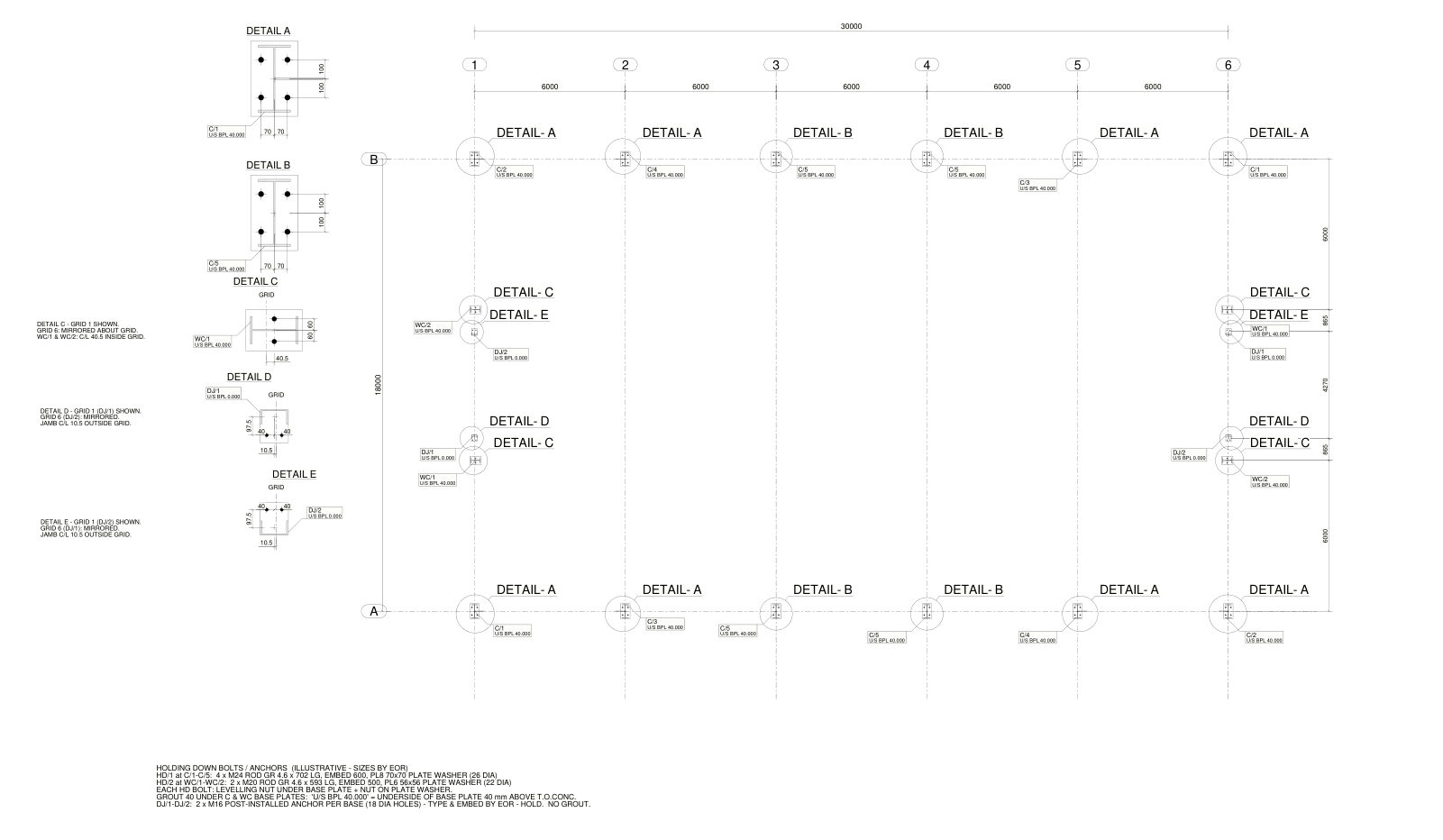
| Holding-down bolt schedule matches the model | rod length, embedment, washer, grout | pass |
| Supplier list totals match the assembly list | cold-rolled list ↔ assembly list | pass |
What the reviews caught
Passing the automated gate is not enough. A separate AI checking agent, with no part in producing the set, reads the sheets the way a fabricator and an erector would and compares them with the model data. A structural engineer of my team then reviews the set before it is released. These are real findings from the two checking rounds on this sample.
Five bases with no mark
The holding-down bolt plan template left 5 of 20 base locations unmarked, including a wind column and both door jambs. All 20 are now marked and match the elevations.
Hole note contradicted the holes
A sheet note said 18 × 22 slotted holes; the model and the NC files drilled 18 mm round. The note now matches what the machine will drill.
Wind column top connection
The intent is a slotted connection so the rafter can deflect without loading the wind column; the model had round holes. The sheets now carry a HOLD note until the engineer confirms the slot.
Wind column bolts 40.5 mm off the grid
The wind column bases sit 40.5 mm inside the grid line and the door jambs 10.5 mm outside, but the base plate details had no grid reference. A concreter setting the bolts on the grid would have missed by 40 mm. The details now show the grid and both offsets.
The package
Everything a fabricator needs to price, order and start cutting, with consistent file names and a drawing register.
- General arrangement: holding-down bolt plan, roof marking plan, side and end elevations
- Shop drawings for every assembly, with grid locations and a material list on each sheet
- Lists: assembly, assembly part, part, bolt summary, bolt erection, bridging and drawing lists
- Cold-rolled order list (CSV) for the purlin and girt supplier
- NC (DSTV) files for plates and members, and DWG or IFC on request
✔ ENGINEER REVIEWED · 1 Nov 2026
Sample project for demonstration only; not for construction. Section sizes are illustrative and not designed.
Send your design drawings
Send the structural drawings, or a link to them. I reply within 24 hours with a fixed price, a delivery date and the RFIs I already see. The first job is US$100.
info@structomat.com