

RHS Hidden Splice
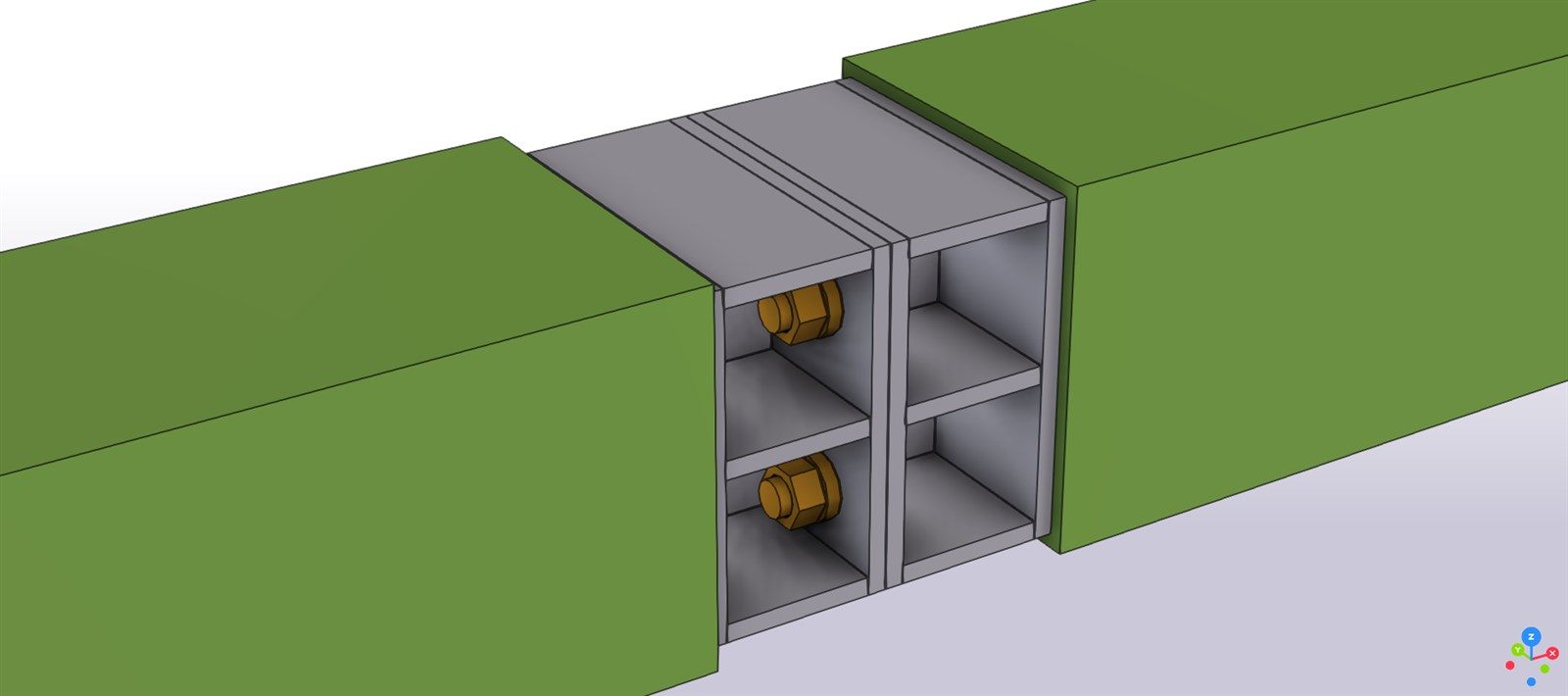
A bolted splice hidden inside the outline of rectangular hollow sections, for Tekla Structures 2026. Pick the main tube and the second tube; the connection cuts both tubes back and creates cap plates, stiffeners, end plates, bolts and shop welds as one parametric connection.
Free plugin · BIM detailing
What it does
A hidden splice keeps the clean outline of a hollow section: there are no flanges outside the tube. Modelled by hand it is fourteen plates, a bolt group, about twenty welds and two cuts per joint, and every one of them has to be repeated for each tube size. The plugin builds them from the tube profile and a few attributes.
Main tube, second tube
A real connection: it shows a connection symbol, follows the tubes when they move and is rebuilt when you change a value. The tubes may touch, overlap or already have a gap.
Any RHS or SHS
Width, height and wall thickness are read from the profile, for each tube separately, so two tubes with different wall thicknesses can be joined. Square, rectangular or rotated sections.
Cross or top and bottom
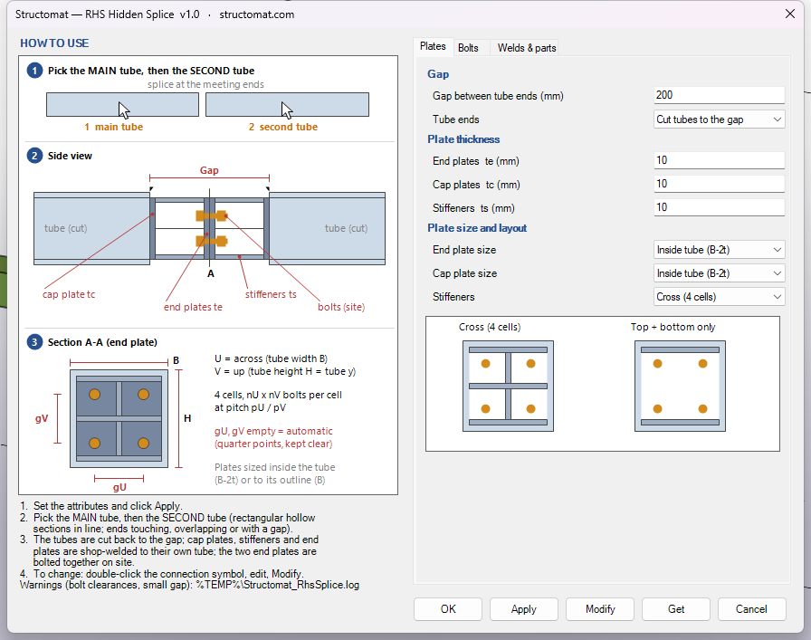
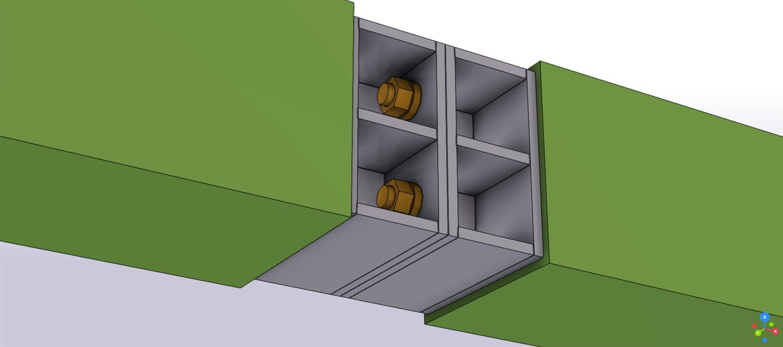
Cap plates, end plates and stiffeners with their own thicknesses. Stiffeners as a cross (four cells) or top and bottom only; end and cap plates inside the tube or to its outline.
Placed clear of the plates
Bolts from your bolt catalog, one or more per cell. By default each bolt group sits at the quarter points and is moved, if needed, so the washer clears the stiffeners and the bolt stays 1.5 d from the plate edge.
Each half in its own assembly
Cap plate welded all around to the tube, every stiffener welded to its cap and end plate. Each half becomes part of its tube’s assembly; the two end plates are bolted together on site.
Warnings you can see
Bolts too close to a stiffener or to the plate edge, or a gap too small for the bolt head and nut, are reported in the Tekla status bar, not hidden in a log file.
How to use it
Set the attributes
Open the connection and set the gap, the plate thicknesses, the stiffener layout, the bolts, welds, material and part numbering. Defaults are filled in.
Pick the two tubes
Click the main tube, then the second tube. The tubes are cut back to the gap, or their existing ends are kept if you prefer.
Change it later
Double-click the connection symbol, change a value and click Modify: plates, bolts, welds and cuts are rebuilt.
Requirements and tests
- Tekla Structures 2026 on Windows.
- Two rectangular hollow sections in line (collinear and concentric).
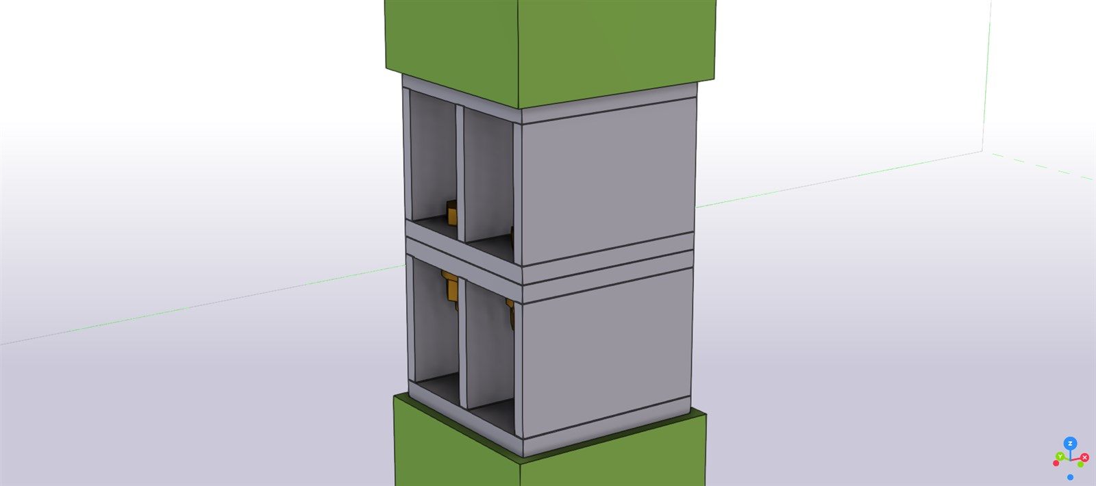
- Tested on 100×100×5 to 300×300×10, square and rectangular, rotated, sloped, vertical and skewed members, tubes drawn in either direction, M12 to M24 bolts, one or 2×2 bolts per cell.
- Bolt standard and size from your own bolt catalog, plate material from your own material catalog.
What it does not do
- It does not design the splice. Plate thicknesses, bolts, welds and the gap come from your structural design and must be checked by a qualified engineer.
- Bolt access for tightening depends on the gap you choose; check it for your erection method.
- Review the model before you produce drawings, as with any automatic detailing.
Get the plugin
The plugin is free. Send me an e-mail with your name, company and Tekla Structures version, and I will reply with the plugin and an installation guide.
Request the plugin Free to use, including on commercial projects; provided as is, without warranty. Your e-mail is used only to send you the plugin and answer your questions. It is not added to a mailing list. See Privacy.Tekla is a registered trademark of Trimble Solutions Corporation. This plugin is made by Structomat and is not affiliated with or endorsed by Trimble. More free tools: structomat.com/tools. Missing a tool? Suggest one.