

From a detailing model to a complete fabrication package
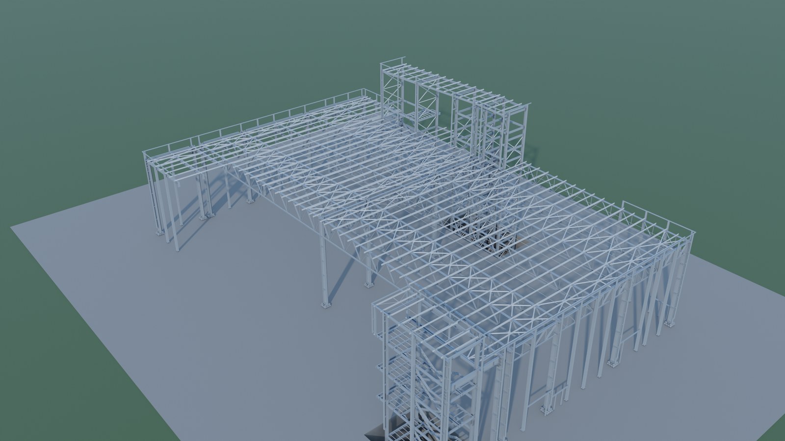
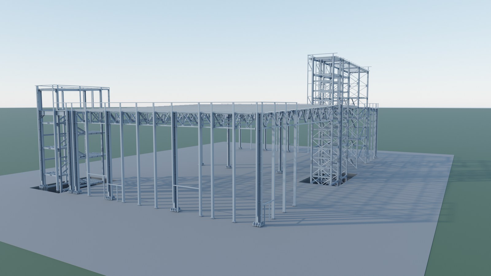
An administrative and storage building with roof trusses, stair and lift towers. The detailing model came from the client; the job was everything after it: checks, numbering, shop drawings, general arrangement sheets, CNC files, lists and a 3D model the site crew can open on a phone.
Case study
The whole workflow in about a minute and a half (no sound).
Step by step
1 · The input: a detailing model, not drawings
The client sent a finished 3D detailing model: 16,471 parts in 1,959 assemblies. The first delivery phase was taken from the model’s own phase filter — 1,660 assemblies and 15,061 parts. Everything else in this case happened after the model: checking it, numbering it and turning it into documents the shop and the site can use.
2 · Checks before a single drawing
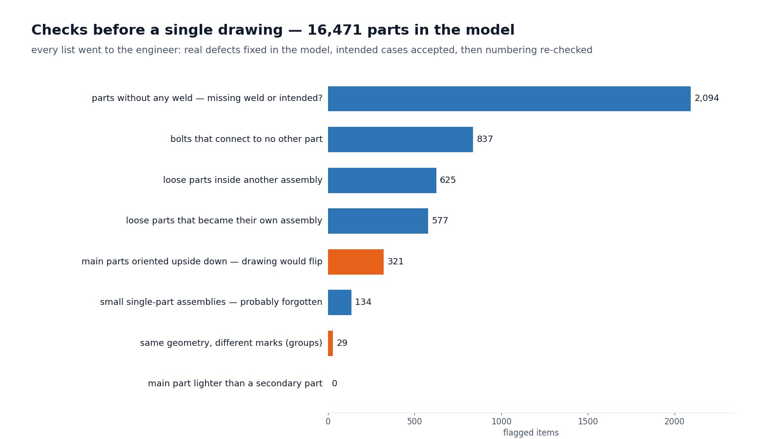
Drawings inherit every model mistake, so the checks came first: parts with no weld, bolts connecting nothing, loose parts that became their own assembly, small assemblies probably meant to belong elsewhere, and main parts oriented upside down — their drawings would have come out flipped. A same-geometry check found 29 groups of identical assemblies with different marks. Each list went to the engineer; real defects were fixed in the model and the numbering was checked again afterwards.
3 · Production, in the right order
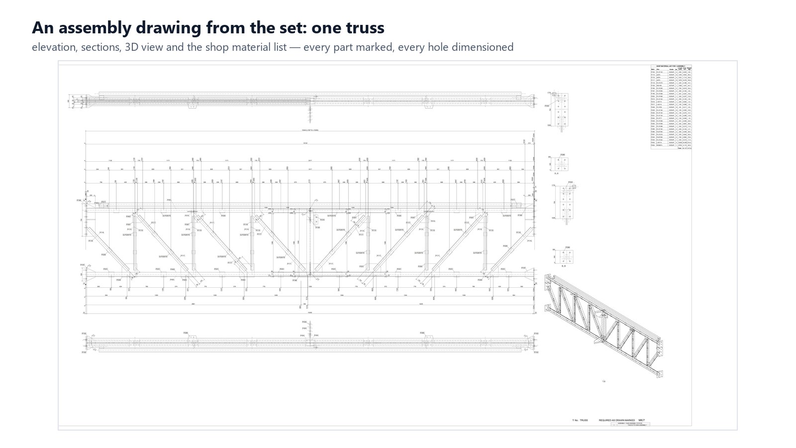
Plates went first: 378 plate parts (9,819 pieces) as DXF files for the cutting machine — because single-part drawings must not repeat what the CNC files already cover. Then 346 assembly drawings and 578 single-part drawings: 924 sheets from one numbering, each with views, sections, a 3D view and the shop material list.
4 · Cleaning what the software leaves behind
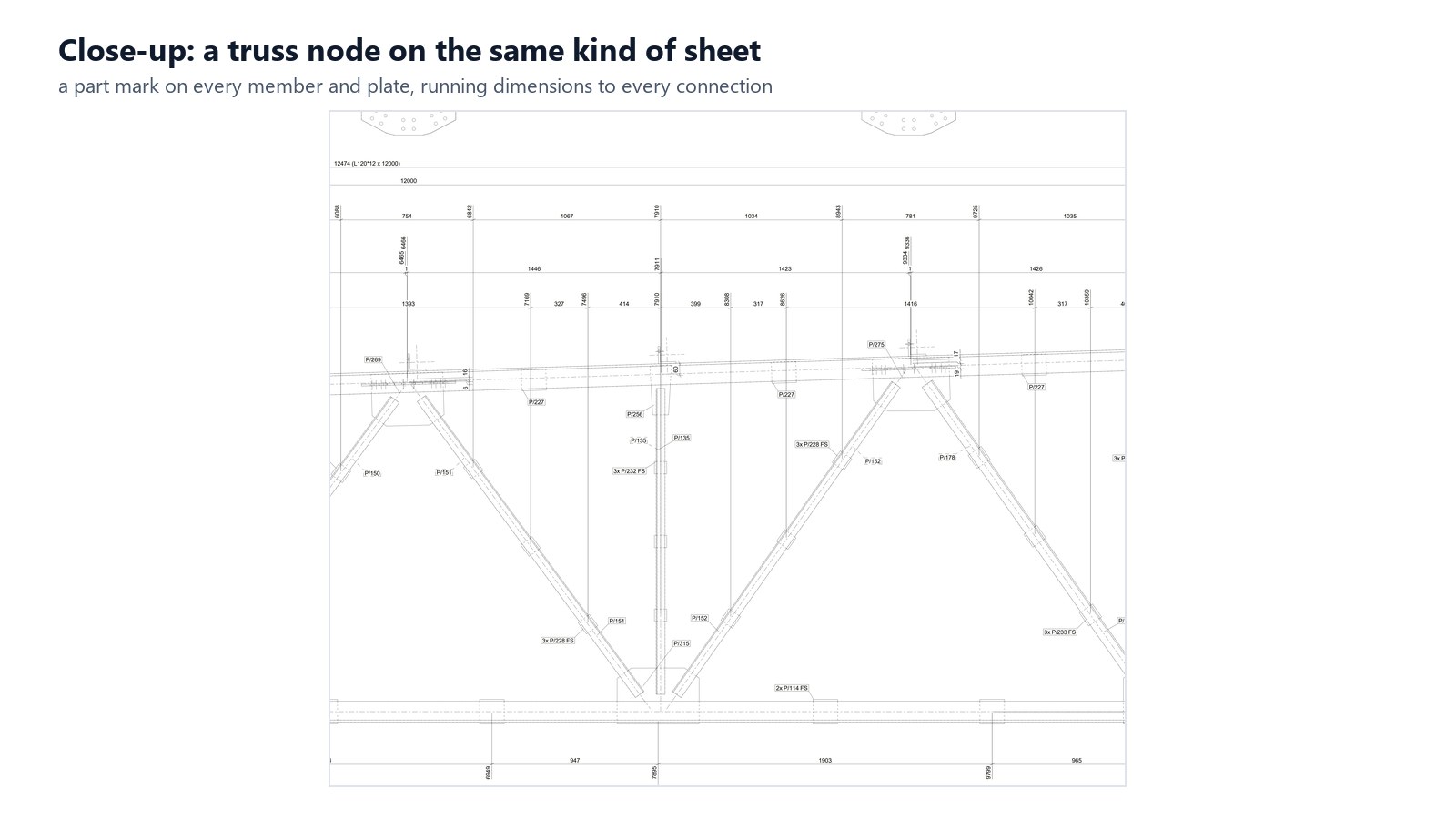
Generated sheets are not finished sheets. Empty views were removed, dimensions left without a reference were deleted, weld symbols were taken off at the engineer’s request, and purlin sheets got dimension chains for every sag-rod hole. Sheet sizes were measured from the drawn extents instead of guessed. The check is always the printed sheet itself — counts alone have missed things before.
5 · General arrangement sheets: the hard part
On a general arrangement sheet the site needs each assembly mark once — not a mark on every bolt and plate in view, which is what the software produces. Adding marks through the programming interface piled them all at the view origin, so the approach turned around: let the software create its marks, and empty the unwanted ones through settings tables built from the model’s own part names. Giving each view only the main parts it needs made building it several times faster.
6 · The first check found three faults
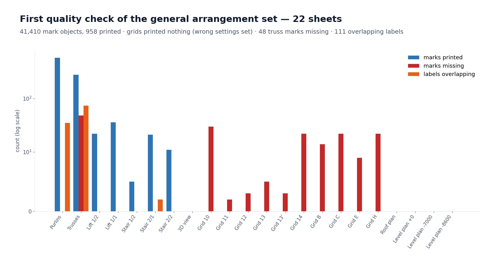
The first quality check over 22 sheets counted 41,410 mark objects and 958 printed marks — and three faults: the grid elevations printed no marks at all (a wrong settings set had been loaded), the truss sheet was missing 48 truss marks (the trusses’ main parts lay just below the view depth), and 111 labels overlapped.
7 · Fixed and checked again
The right settings were reloaded, the view depth was extended, overlapping labels were moved apart and every sheet was renamed after its view; the sheets were produced through the detailing software’s own dialog, driven by screen automation. The engineer made the final hand edits. Result: 21 general arrangement sheets, also merged into a single DWG with a fixed layout.
8 · Requests after the client's review
The client asked for extra dimensions — end-bolt to end-bolt on the trusses, hole to hole on the braces. The engineer placed them by hand on one pilot sheet; I read the pattern from that sheet and repeated it on every similar sheet, checking each new dimension against the pilot. The bolt list was merged by grade at the engineer’s request, without changing the model — and the list states the merge in a footnote.
9 · Export without surprises
All sheets were exported to DWG, then checked file by file: layer standard, plot setup, and the frames around text masks switched off — those printed as boxes around every dimension once before. Two lessons from the way: a CAD session left idle for hours silently drops plot settings, so each run starts in a fresh one; and a file is never saved after a failed write, because that is how a drawing got corrupted once.
10 · The package
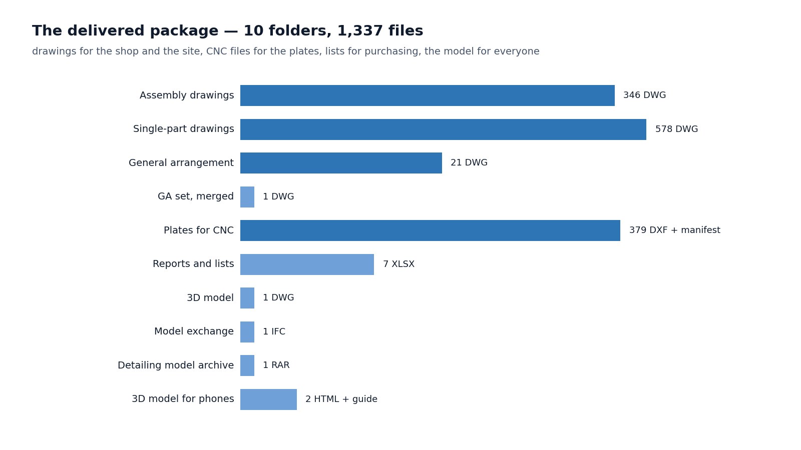
10 folders, 1,337 files: assembly and single-part drawings, the general arrangement set, CNC files, seven lists, and a 3D model that opens offline on a phone so the crew can find any assembly mark on site. The engineer exported the 3D DWG, the IFC and the model archive; the rest came from the pipeline. The engineer reviewed the drawings before they went to the client.
In numbers
What stays with people
Decisions
What the first phase includes, what goes on the general arrangement sheets, which marks to suppress, removing weld symbols, the bolt-list merge and the final hand edits were the engineer’s decisions. I proposed, produced, checked and documented them.
Responsibility
The model’s members and connections belong to the engineer of record. Drawings were reviewed by the engineer before release to the shop.
Have a detailing model that needs drawings?
Send the model and your drawing standard. The first step is a model check, before a single sheet is produced.
info@structomat.com