

From a DWG detail to a signed calculation report
A steel fascia and soffit sub-frame along a roof slab edge: read from an architectural drawing, handed over as IFC4, analysed, designed to AISC 360-16 and documented — with the key numbers checked against independent calculations.
Case study
The whole workflow in about a minute and a half (no sound).
Step by step
1 · The input: a section detail
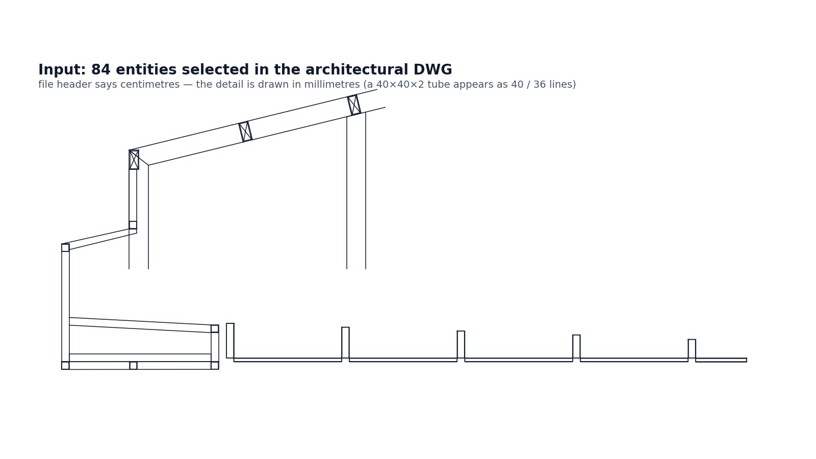
The architect shared a section detail of a steel fascia and soffit sub-frame along a roof slab edge, with a note that the structural calculation and wall thicknesses belong to the subcontractor. What I received was a selection of 84 entities in a DWG. The first trap was in the file itself: the header declares centimetres, but the detail is drawn in millimetres — a 40×40×2 tube appears as lines 40 and 36 units apart.
2 · Geometry read from the drawing
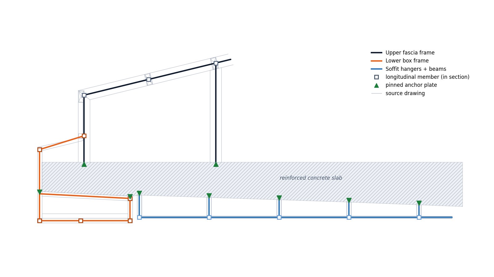
Each analysis node is searched for in the drawing — box centres, line pairs, rafter faces — and the script stops if one is missing. Where the analysis model deliberately departs from the drawing (a purlin moved 12 mm onto a post, a longitudinal member 27 mm onto the frame line, a sloped tube 30 mm onto the post it connects to) the offset is measured and written into the report.
3 · A representative strip, not the whole roof
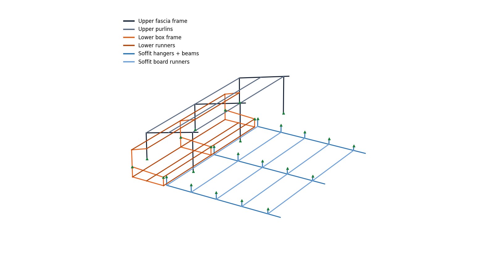
The engineer set the scope: the section repeats every 1.83 m, so three frames with continuous runners form a 3.66 m strip — 56 physical members, 97 analytical members and 27 pinned anchor plates to the slab. With two spans, the middle frame takes about 1.25 times the runner load, and the end frames see the runners’ end rotation; both effects stay in the design.
4 · IFC4 as the hand-off, then the finite element model
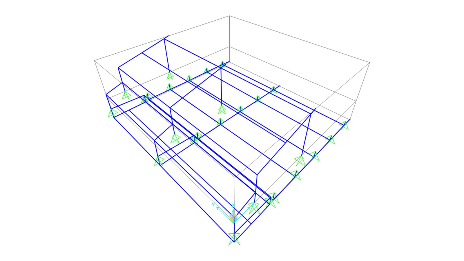
I wrote an IFC4 file with both the physical members and an analytical model (curve members, point connections with pinned boundary conditions). The finite element model was then built from the IFC, not from my own list: reading it back matched 97 of 97 members within 0.1 mm. Health check: zero negative stiffness eigenvalues, and the self-weight reaction equals the hand calculation (3.052 kN, difference 0.00%).
5 · Loads that can be checked by hand
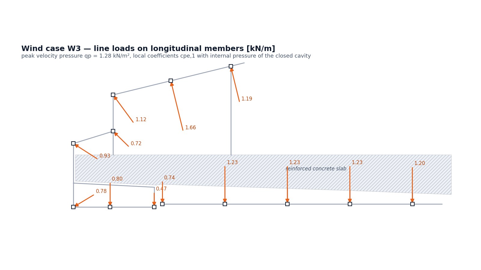
Cladding (0.20 and 0.35 kN/m²), snow with sliding snow from the steeper roof behind, and four wind cases (peak velocity pressure 1.28 kN/m², local cpe,1 coefficients, internal pressure of the closed cavity — EN 1991-1-3 / -4). Each surface load becomes a line load on the runner it actually bears on, by tributary width. For all 11 load patterns, the applied total equals the sum of support reactions to 0.000 kN.
6 · What the checks changed
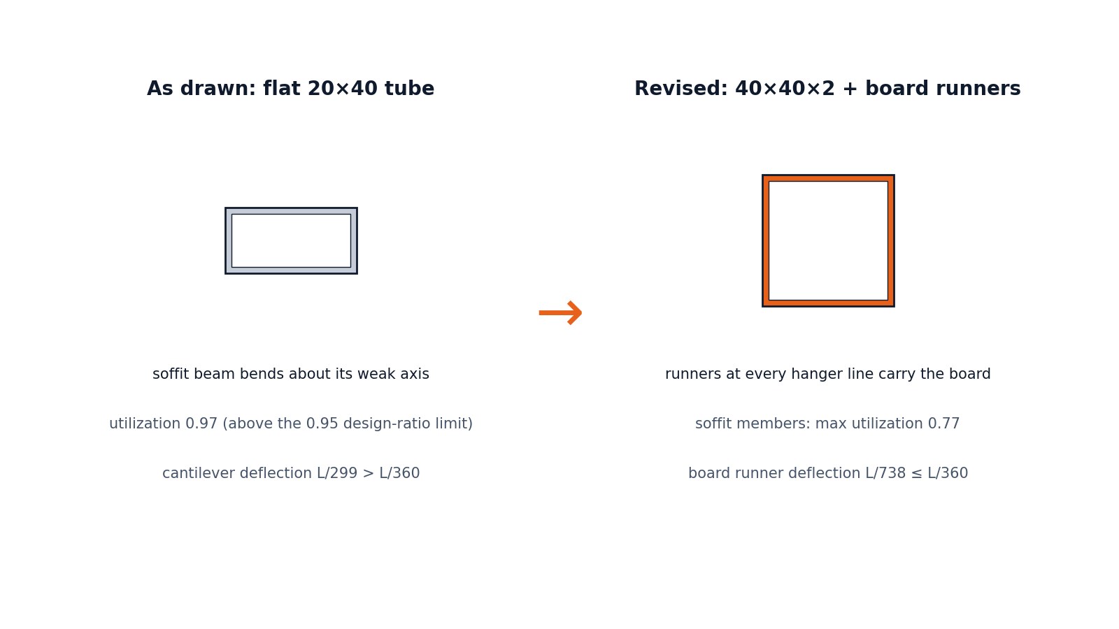
The drawing showed the soffit beams as flat 20×40 tubes. Bending about their weak axis gave a utilization of 0.97 — above the 0.95 design-ratio limit — and a cantilever deflection of L/299 against L/360 for plaster on board. The software’s one-line summary still said “all members passed”; its own detailed table flagged the member, so I read the detailed tables. The modal check also showed 2.5–3.1 s modes: the soffit frames were not tied to each other. The engineer decided on 40×40×2 tubes with board runners at every hanger line — the soft modes disappeared and the soffit’s highest utilization dropped to 0.77.
7 · Member design — Direct Analysis Method
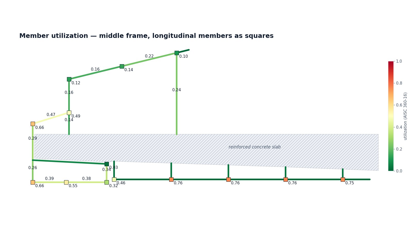
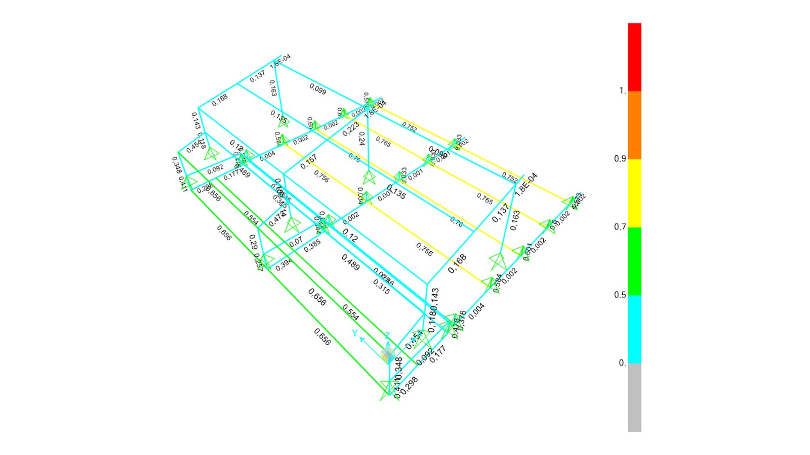
All 29 combinations (24 strength, 5 serviceability) run as P-Δ nonlinear cases. Member checks follow AISC 360-16 with the Direct Analysis Method; I confirmed from the property-modifier table that the 0.8·EI and 0.8·EA reduction was actually applied to all 97 members, and notional loads are explicit load patterns. Highest utilization: 0.77 (soffit board runner); the upper frame stays below 0.25.
8 · Serviceability on nominal stiffness
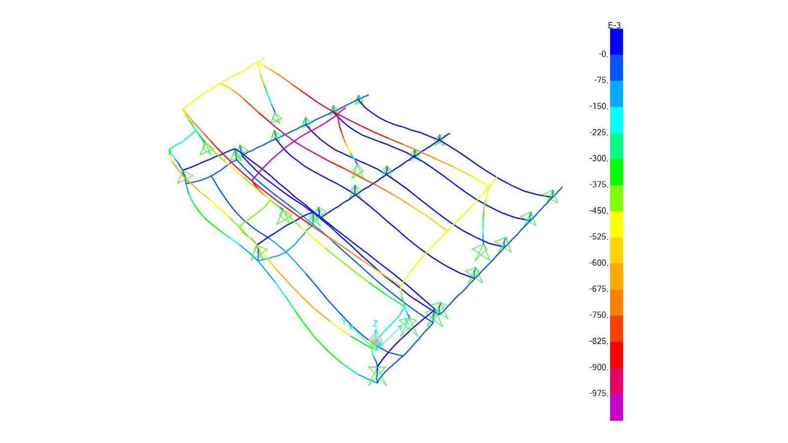
Deflections are taken from a separate analysis on nominal stiffness (AISC 360-16 C2.3), checked span by span — not per finite-element piece. Largest horizontal movement at the top of the fascia: 0.94 mm (L/617, limit L/200). The soffit runners reach L/738 against L/360 even with the reduced design stiffness.
9 · Anchor plates, with an honest scope
Tension and shear are taken from the same combination and the same plate, then shared between two M8 mechanical expansion anchors per plate (an assumption stated in the report). Against the manufacturer’s single-anchor design values the worst interaction is 0.73. Concrete cone, edge breakout, pry-out and splitting were not checked here by decision; the report says so in a red box and names the plate closest to the slab edge.
10 · The deliverable
A 21-page calculation report with 13 figures and 20 tables: model checks, load verification, combinations, member design, serviceability, reactions and anchors, plus a box listing where the design departs from the architectural detail. Construction documents are reviewed and signed by a licensed partner engineer.
In numbers
What stays with people
Decisions
The representative strip, the support conditions, the cladding and wind assumptions and the change from the drawn 20×40 tubes were the engineer’s decisions. I proposed, checked and documented them.
Responsibility
Anchor checks in concrete still belong to the anchor manufacturer’s software, and the calculation report going to construction is reviewed and signed by a licensed partner engineer.
Have a detail that needs a calculation?
Send the drawing or the IFC and a short description of what has to be checked.
info@structomat.com