

A crane canopy: three support decisions and the traps between them
A pitched steel canopy over a concrete basin, with a 5 t bridge crane on column brackets. It started as a 2D steel drawing in a tender package. Twice, fixing one check moved the problem somewhere else before the design settled — this is the sequence, with the numbers.
Case study
The whole sequence in about a minute and a half (no sound).
Step by step
1 · From a tender drawing to a 3D model
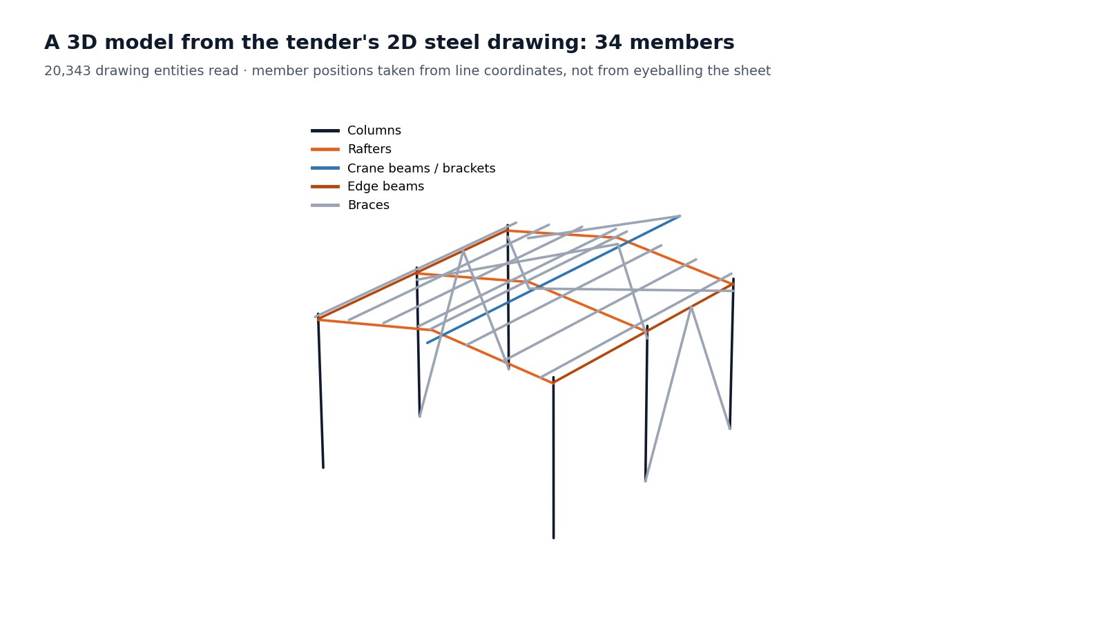
The input was the steel drawing of a tender package: 20,343 entities in one DWG. I took off the member list and built a 3D detailing model from line coordinates — 34 members: six columns, three portal frames, a crane beam under the ridge, edge beams, purlins and braces. The scale came from the grid: one drawing unit was 50 mm, although the file header said millimetres.
2 · The engineer reworked the model
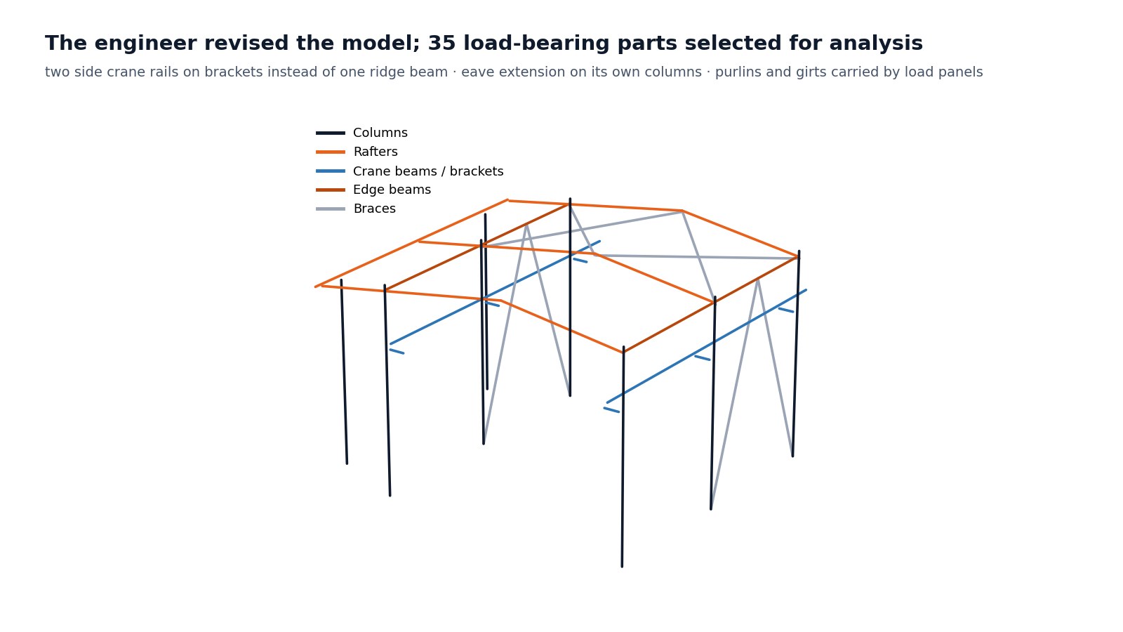
The engineer then changed the model: the single ridge crane beam became two side crane rails on brackets, an eave extension got its own columns, and roof purlins and wall girts were added on all four sides. The lesson I keep: read the live model, never my own build script. The engineer selected the 35 load-bearing parts for analysis; purlins and girts carry the cladding through load panels. A name-based classifier would have dropped the crane rails, so this project got its own classification.
3 · Sliver members and silently lost panels
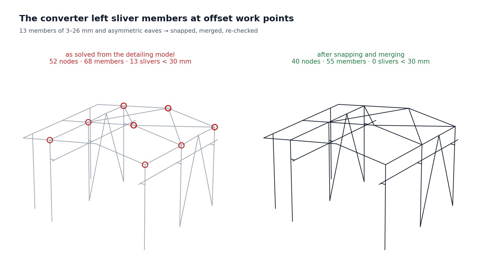
Work points in a detailing model are legitimately offset — braces 40 mm below the rafters, edge beams 26 mm above. The converter could not merge them and left 13 sliver members of 3–26 mm and asymmetric eaves. I snapped the axes, levelled the eaves and merged nodes: 52 → 40 nodes, 68 → 55 members. One more trap: after levelling, four corners of a gable panel fell on one node and the solver silently rejected 5 of 14 load panels. Corners are now de-duplicated, and panels are counted after import.
4 · First design run: the braces
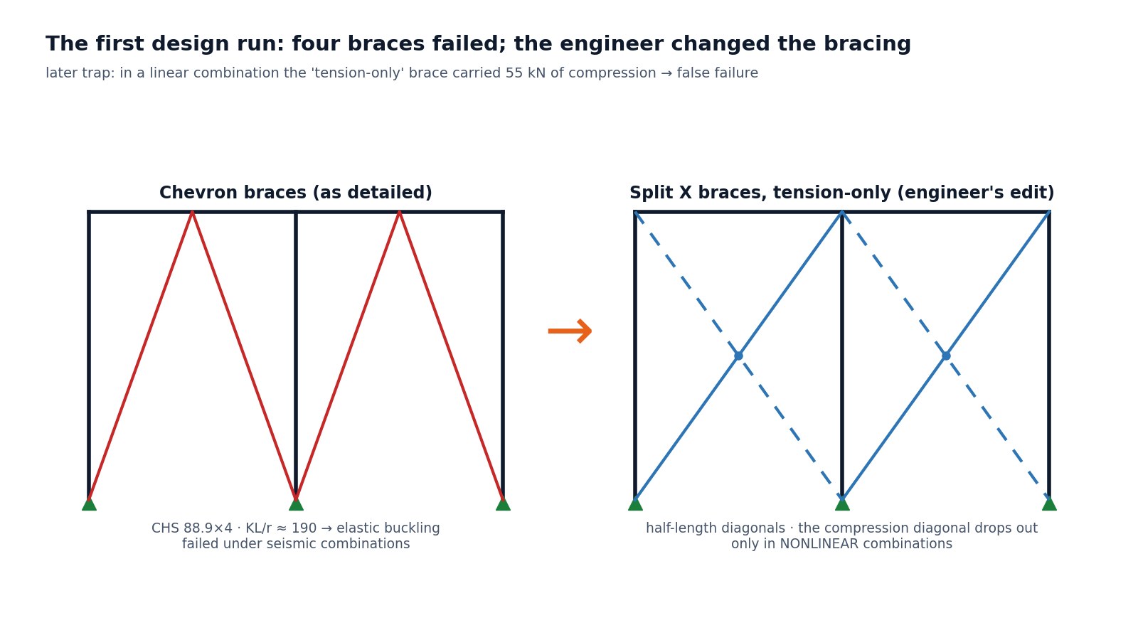
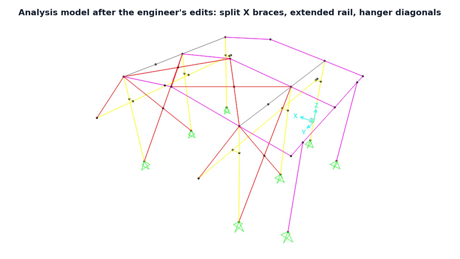
Loads: exposure category 0, no snow, roof live load 1.0 kN/m², cladding 0.50 kN/m², seismic importance factor 1.5, crane loads from the crane data. The first design run flagged the chevron braces: CHS 88.9×4 with a slenderness near 190 buckles elastically. The engineer split them into X braces at the crossing, made them tension-only, extended the crane rail by 1 m and added hanger diagonals; I added a case with the crane at the cantilever tip. Then the trap: the new combinations were linear, so the ‘tension-only’ brace carried 55 kN in compression over its full 6.68 m — a false failure that disappears once the combinations are nonlinear.
5 · Direct Analysis, verified in the tables
All combinations run as P-Δ nonlinear cases. I confirmed from the property-modifier table — not from the member query, which does not show it — that the 0.8·EA and 0.8·EI reduction was applied to every member. Strength passed everywhere. Serviceability did not.
6 · Fixing the drift broke the anchors
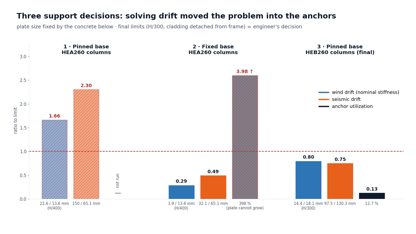
With pinned bases, the transverse direction had only frame action: wind drift 22.6 mm against H/400 = 13.6 mm, seismic drift 150 mm against 65.1 mm. The engineer fixed the bases — drift dropped to 3.9 and 32.1 mm and every check passed. Then the base plate went into the connection software: a base moment of about 61 kNm sent the anchors to 398 % and the welds to 100 %. The plate could not grow: the concrete below it limits its size.
7 · Pinned again — with stiffer columns and the right stiffness
Final decision: pinned bases, columns HEA260 → HEB260. Per AISC 360-16 C2.3 the 0.8 reduction is for strength and stability; drift uses nominal stiffness: 14.4 mm against H/300 = 18.1 mm (with reduced stiffness it would be 17.9 mm and fail). My first ‘nominal’ run was wrong — I had unlocked the model before redesign, the modifiers stayed at 0.8 and I reported 17.9 as nominal. The correct order is preference → analysis → design → analysis, and I check the modifier table every time. Seismic drift 97.5 mm against 130.3 mm, with the limit for cladding detached from the frame. Anchors 12.7 %, welds 20.6 %.
8 · A deflection ratio is not a strength ratio
The software’s summary listed 0.60 as the highest ratio — a deflection-type ratio on a 305 mm crane bracket under a serviceability combination. Strength governs at 0.54, on a brace. The 62-page report (54 calculation pages + the 8-page base plate report) states which is which, and notes that crane girder fatigue and web crippling are outside its scope.
9 · Back to the detailing model for fabrication
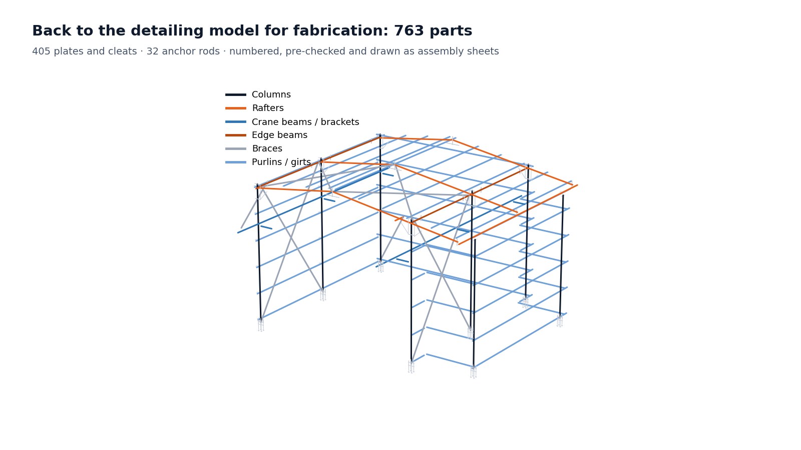
Connections, base plates and anchor rods were detailed in the model — 763 parts, 32 anchor rods. Before drawing I ran pre-checks (clashes, same-mark consistency, numbering), then produced the assembly sheets. After a later model revision the sheets were reissued and merged into one DWG.
In numbers
What stays with people
Decisions
The model rework, the X bracing, fixed and then pinned bases, HEB260 columns, the H/300 limit and the seismic drift limit for detached cladding were the engineer’s decisions. I proposed, checked and documented them — including where my own first ‘nominal’ run was wrong.
Responsibility
Crane girder fatigue and web crippling are outside the report, and it says so. The calculation report going to construction is reviewed and signed by a licensed partner engineer.
Is one fix breaking another check?
Send the model or the drawings and the check that keeps failing. I will trace it and show the options with numbers.
info@structomat.com