

A crane building: from a detailing model to a reaction package for the foundation designer
A single-storey steel building with a 2 t bridge crane on column brackets. The analysis model came from an existing 3D detailing model; the deliverables were a calculation report and a reaction package for the engineer designing the foundations in other software.
Case study
The whole workflow in about a minute and a half (no sound).
Step by step
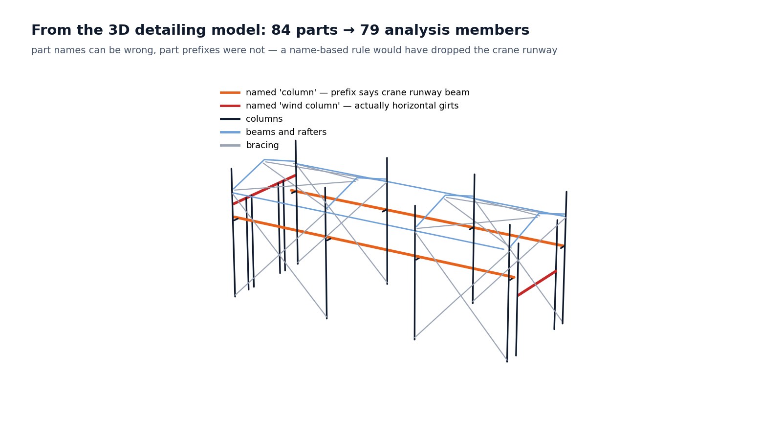
1 · From the detailing model: names lie, prefixes don't
The input was a 3D detailing model with 84 parts; 79 became analysis members (the door frame stayed out). The part names were not reliable: the crane runway beams and brackets were named ‘column’, and two parts named ‘wind column’ were horizontal girts. The part prefixes were right, so the classification used prefixes. A name-based rule would have dropped the crane runway as non-structural.
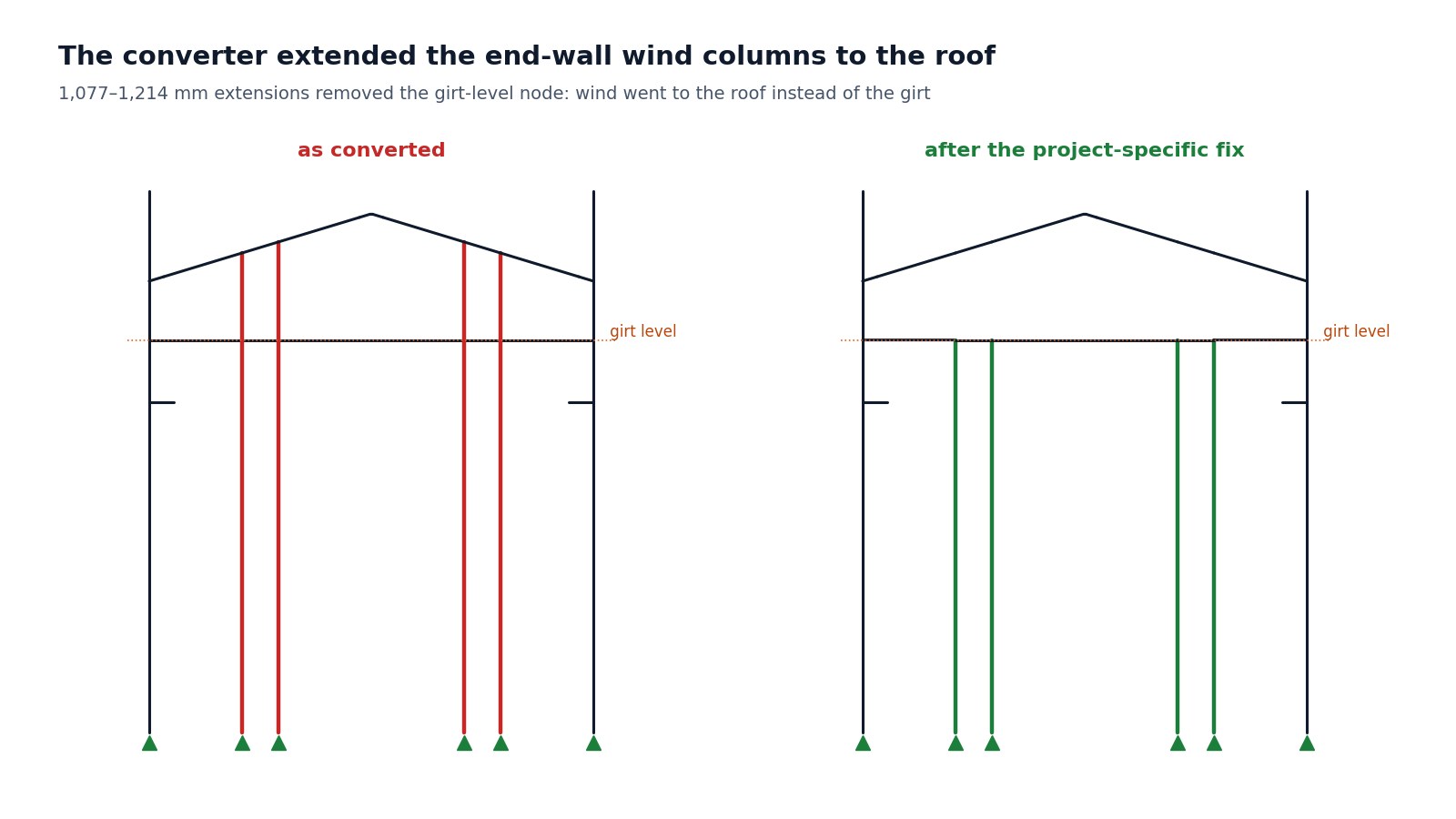
2 · The converter broke a girt connection
The geometry converter extends columns up to the roof plane — right for main columns, wrong for end-wall wind columns that stop at a girt. It extended four of them by 1,077–1,214 mm; the node at girt level disappeared, the girt ran through the columns and the end-wall wind went to the roof. In the same model a 306 mm extension was a legitimate cut allowance: the size of the extension is the tell. A project-specific step restored the connection.
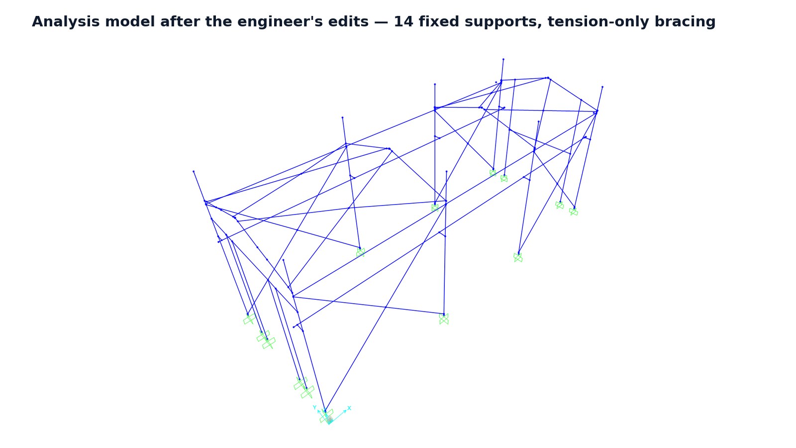
3 · The engineer's edits — and a 42 % hole in the wind
The engineer edited the analysis model by hand: roof brace ends moved to truss nodes, vertical braces joined, end releases, end-wall panels trimmed. I then measured load-panel coverage by area, not by count: 42 % of the left end wall had no panel (19.38 of 33.13 m²) — wind load that simply was not there. Restored to 33.04 m². The health check stayed clean.
4 · Loads, read back from the reactions
Ground snow 1.16 kN/m² with drift behind the 1.07 m parapet gives 2.14 kN/m² on the roof; temperature ±35 °C; seismic with a different behaviour factor per direction (braced one way, moment frames the other); crane loads at the bracket tips. The crane load module also added the runway beam’s self-weight, although the beam was already a member in the model — a double count I removed. Every load pattern balances: dead load 300.52 kN, snow 191.94 kN, roof live load 89.69 kN = 0.999 kN/m² against the 1.0 entered.
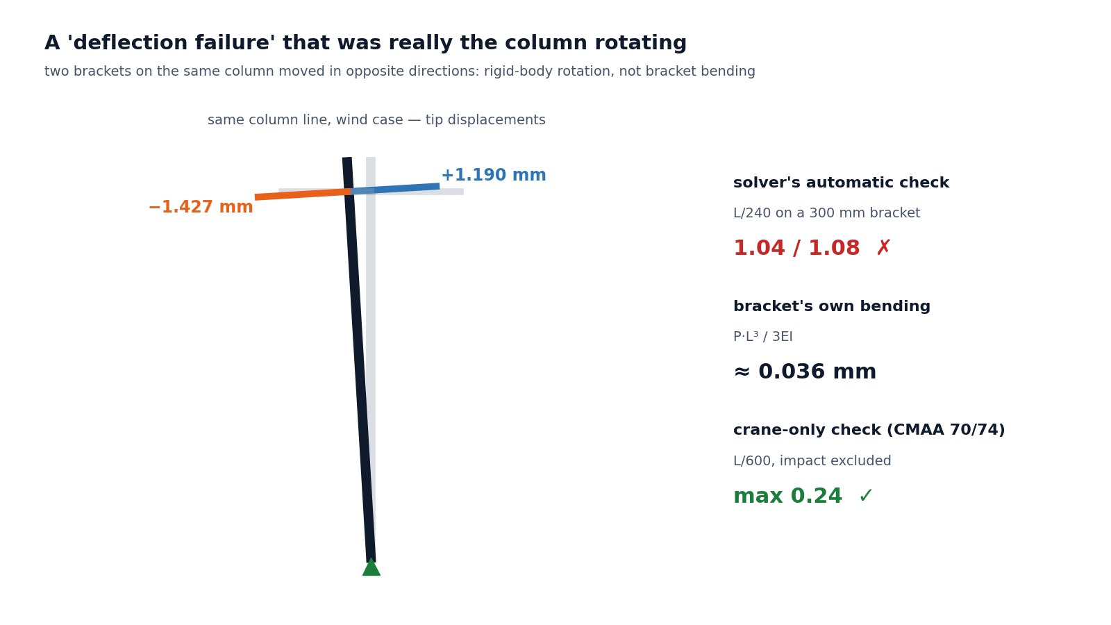
5 · A 'deflection failure' that was column rotation
All members passed strength, highest 0.52 (a column). But the automatic check failed two 300 mm crane brackets at L/240. The measured value was not bending: on the same column line one bracket tip moved up 1.190 mm and the other down 1.427 mm under wind — the column rotating; the bracket’s own bending is about 0.036 mm. The engineer chose a crane-only criterion (CMAA 70/74, L/600, impact excluded): worst 0.24. The automatic check was switched off for those brackets, with the reason written into the report.
6 · A reaction package for the foundation designer
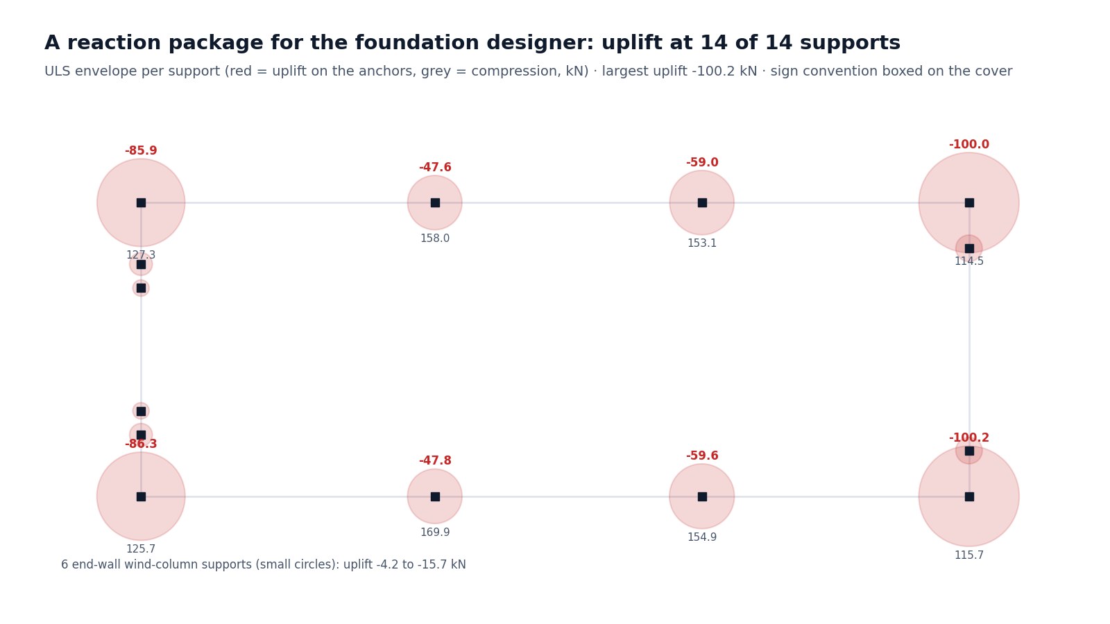
The foundations were designed by another engineer in other software, so they received a 13-page PDF and a spreadsheet: support layout and names, nine load patterns, the combination envelope — and the sign convention in a box on the cover, with a real example: the analysis reports the force the support applies to the structure; the foundation receives the opposite. All 14 supports see uplift; the largest is −100.2 kN. An example value I first typed by hand was wrong; examples are now read from the document’s own tables.
7 · Revision and the final report
The final site investigation arrived later: the short-period design acceleration changed by +0.23 % — on its own not a reason to re-analyse, so only the source document was replaced. The engineer’s three connection reports were appended unchanged to the 62-page calculation: 116 pages. Construction documents are reviewed and signed by a licensed partner engineer.
In numbers
What stays with people
Decisions
Fixed bases, the snow and temperature values, the direction-dependent seismic system, the hand edits to the analysis model and the crane-only bracket criterion were the engineer’s decisions. I proposed, checked and documented them.
Responsibility
Foundation design and the concrete checks of the anchors stay with the foundation designer, and the package says so. The calculation report going to construction is reviewed and signed by a licensed partner engineer.
Have a detailing model that needs an analysis?
Send the model export and a short description. Reactions come with a sign convention your foundation designer can use.
info@structomat.com