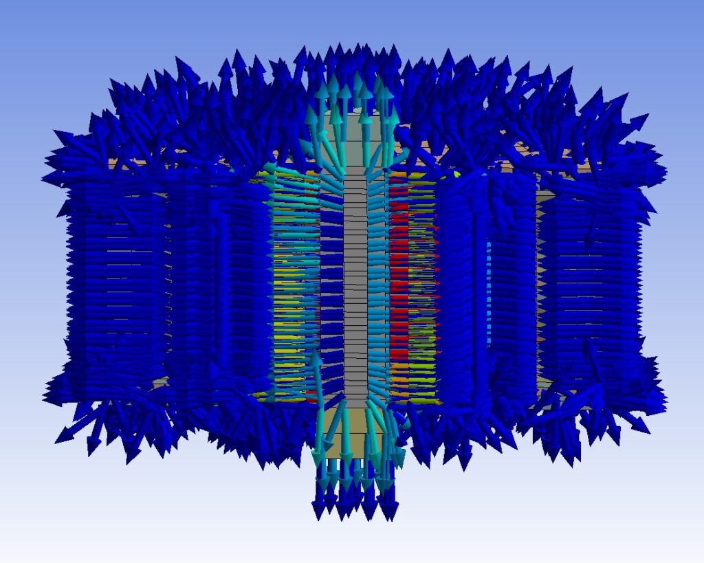
In this simulation, we will analyze the behavior of a lead rubber bearing (LRB) isolator using the finite element method.
The lead rubber bearing isolator, invented in 1975 by New Zealand mechanical engineer W.H. Robinson, consists of steel-reinforced rubber layers, steel plates, and a lead core at its center.
After earning his degree in mechanical engineering, Bill Robinson realized that he could not produce high-quality products without a deeper understanding of materials. This led him to pursue a degree in metallurgical engineering as well.
It is said that before inventing the lead rubber bearing, he spent a year locked in his office with the periodic table, trying to determine which element to use to fill the central void of the isolator.
After its invention, the lead rubber bearing found applications in numerous projects and various types of structures.
On his 81st birthday, Google honored him with a Google Doodle to commemorate his contributions.

Once a widely popular element, lead has been used in various products—from gasoline, paints, and batteries to glass—despite its known harmful effects on living organisms for over a thousand years.
Several factors contributed to its popularity:
- Its low melting point compared to steel, making it easy to work with even at room temperature.
- It is one of the heaviest metals, which made it useful in many applications.
- However, its strength is relatively low.
Rubber in Isolator Manufacturing
The rubber used in isolator manufacturing is a hyperelastic material. Although its stress-strain curves are nonlinear, it returns to its original shape elastically even after very large deformations when the load is removed. Therefore, its behavior is nonlinear but elastic.
To model these nonlinear stress-strain curves, numerous researchers have proposed various models. We are familiar with such complex, nonlinear behaviors from soil mechanics, where soils are often represented by nonlinear springs.
Steel in Isolators
While rubber and lead are used for their flexibility and energy dissipation, steel is employed where strength and rigidity are required.
Behavior of Lead During Seismic Events
During strong ground motions, when seismic waves from tectonic plate movements reach the isolator, the following occurs at the atomic level:
- The planes formed by lead crystals first slip relative to each other.
- Then, they begin to frictionally interact, generating heat.
- The temperature of the lead rises significantly.
In large-scale isolators, this temperature increase can reach 100-150°C, bringing the lead close to its melting point.
Heat Dissipation in Isolators
The lead core is completely encapsulated by:
- Steel plates at the top and bottom,
- Rubber layers on the sides.
Since rubber has very low thermal conductivity, heat cannot easily escape through the sides. Instead, heat is transferred:
- Through the top and bottom steel plates to the surrounding air,
- And into the structural elements to which the plates are attached.
The Journey of Energy: From Earth’s Core to Seismic Isolators
The heat energy originating from the molten metals in Earth’s core undergoes a fascinating transformation:
- Heat Energy in Earth’s Core:
- The Earth’s core, composed of molten iron and nickel, generates immense heat due to radioactive decay and residual heat from planetary formation.
- Conversion to Kinetic Energy:
- This heat drives the movement of tectonic plates, converting thermal energy into kinetic energy.
- The movement of these plates causes seismic waves during earthquakes.
- Conversion Back to Heat Energy in Isolators:
- When seismic waves reach a structure equipped with seismic isolators (like lead rubber bearings), the kinetic energy is absorbed by the isolator.
- In the isolator, the lead core dissipates this energy through friction, converting it back into heat energy.
Behavior of Lead Rubber Bearings Under Extreme Conditions
The lead rubber bearing (LRB) isolator is a critical component in seismic protection, but its performance can degrade under extreme conditions. Here’s a detailed explanation of its behavior:
1. Effect of Temperature on Lead Core
- As the temperature of the lead core increases, its yield strength decreases.
- At the atomic level, the bonds between lead crystals break, and the crystals scatter.
- This reduces the lead’s ability to resist horizontal forces, diminishing the isolator’s energy dissipation capacity with each oscillation.
2. Role of Rubber Layers
- While the lead core struggles with horizontal forces, the rubber layers take on the challenge of resisting vertical loads.
- Under extreme conditions, the rubber can undergo shear deformations of 150-200%, far exceeding the deformation limits of materials like steel or concrete.
- For comparison:
- Steel: Typically fails at 17% elongation under tension.
- Concrete: Fails at just 0.5% compression.
- For comparison:
3. Vertical Stiffness Degradation
- With each oscillation, the isolator’s vertical stiffness decreases.
- Due to second-order effects caused by horizontal displacements, the vertical stiffness can drop to one-fifth of its original value in the fully vertical position.
4. Hysteretic Behavior
- The isolator’s response at any moment depends on:
- Its prior experiences (before and during the earthquake),
- The movement of the structure above it,
- The behavior of the ground below it.
- This hysteretic behavior means the isolator’s performance is highly dependent on its history of loading and deformation.
5. Critical Scenarios
- If the isolator experiences maximum horizontal deformation while simultaneously subjected to maximum vertical tension or compression, the resulting stresses and strains in the rubber, lead, and steel can lead to catastrophic failure.
- At its weakest moment, a strong “punch” from seismic forces could knock out the isolator, rendering it ineffective.
Challenges in Isolator Testing and Design
Seismic isolators, such as lead rubber bearings (LRBs), are critical for protecting structures during earthquakes. However, their performance under real-world conditions depends heavily on rigorous testing and design. Here’s an analysis of the challenges and requirements for effective isolator testing and implementation:
1. Limitations of Current Testing Protocols
- Static vs. Dynamic Testing:
- Many testing setups cannot simulate the dynamic conditions of a real earthquake.
- Testing protocols often focus on:
- Vertical load capacity under static conditions (no earthquake),
- Horizontal displacement capacity under a fixed vertical load (simulated earthquake).
- In some test setups, the isolator’s vertical movement is completely fixed, which does not reflect real-world behavior.
- Incomplete Simulation:
- Testing setups that cannot apply both horizontal and vertical loads dynamically and simultaneously may miss critical failure modes caused by hysteretic behavior.
- This can lead to isolators failing under smaller earthquakes than they were designed for, rendering them unusable.
2. Real-World Implications
- Unexpected Failures:
- Isolators that perform well in simplified tests may fail in real earthquakes due to:
- Simultaneous horizontal and vertical loading,
- Hysteretic effects (history-dependent behavior).
- This can result in isolators sustaining damage or failing under seismic loads smaller than their design limits.
- Isolators that perform well in simplified tests may fail in real earthquakes due to:
3. Requirements for Effective Isolators
- Comprehensive Testing:
- Testing setups must simulate realistic earthquake conditions, including:
- Dynamic horizontal and vertical loading,
- Hysteretic behavior under cyclic loading.
- This ensures that isolators can handle the complex forces experienced during an earthquake.
- Testing setups must simulate realistic earthquake conditions, including:
- Robust Design:
- A well-designed isolator should:
- Dissipate energy effectively through lead core deformation and rubber flexibility,
- Maintain vertical stiffness under large horizontal displacements,
- Withstand simultaneous extreme loads without failure.
- A well-designed isolator should:
- Performance in Extreme Conditions:
- A properly designed and tested isolator will:
- Absorb and dissipate energy during the largest possible ground motion,
- Protect the structure from seismic hazards, ensuring its safety and functionality.
- A properly designed and tested isolator will: